Toyota Venza: Terminals Of Ecu
TERMINALS OF ECU
1. CHECK POWER BACK DOOR ECU (POWER BACK DOOR MOTOR UNIT)
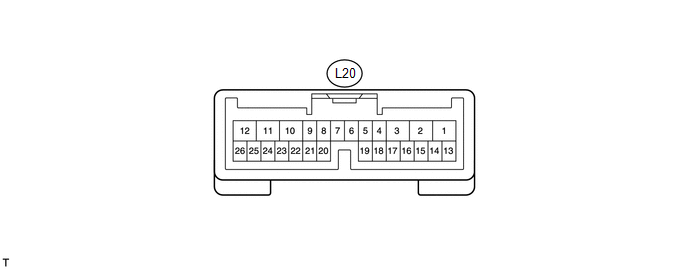
(a) Disconnect the L20 ECU connector.
(b) Measure the voltage and resistance according to the value(s) in the table below.
|
Tester Connection |
Wiring Color |
Terminal Description |
Condition |
Specified Condition |
|---|---|---|---|---|
|
L20-10 (ECUB) - Body ground |
P - Body ground |
Battery power supply |
Always |
11 to 14 V |
|
L20-12 (B) - Body ground |
LG - Body ground |
Battery power supply |
Always |
11 to 14 V |
|
L20-8 (IG) - Body ground |
SB - Body ground |
IG power supply |
Ignition switch ON |
11 to 14 V |
|
L20-8 (IG) - Body ground |
SB - Body ground |
IG power supply |
Ignition switch off |
Below 1 V |
|
L20-17 (MSW) - Body ground |
R - Body ground |
Power back door main switch signal |
Power back door main switch not pushed |
Below 1 Ω |
|
L20-17 (MSW) - Body ground |
R - Body ground |
Power back door main switch signal |
Power back door main switch pushed |
10 kΩ or higher |
|
L20-4 (DS1) - Body ground |
L - Body ground |
Power back door closer switch signal |
Power back door closer switch on |
Below 1 Ω |
|
L20-4 (DS1) - Body ground |
L - Body ground |
Power back door closer switch signal |
Power back door closer switch off |
10 kΩ or higher |
|
L20-15 (OSL) - L20-14 (OSE) |
Y - V |
Power back door touch sensor LH signal |
Power back door touch sensor LH not pressed |
950 to 1050 Ω |
|
L20-15 (OSL) - L20-14 (OSE) |
Y - V |
Power back door touch sensor LH signal |
Back door touch sensor LH pressed |
Below 100 Ω |
|
L20-13 (OSR) - L20-14 (OSE) |
R - V |
Power back door touch sensor RH signal |
Back door touch sensor RH not pressed |
950 to 1050 Ω |
|
L20-13 (OSR) - L20-14 (OSE) |
R - V |
Power back door touch sensor RH signal |
Power back door touch sensor RH pressed |
Below 100 Ω |
|
L20-11 (GND) - Body ground |
W-B - Body ground |
Ground |
Always |
Below 1 Ω |
If the result is not as specified, there may be a malfunction on the wire harness side.
(c) Reconnect the L20 ECU connector.
(d) Initialize the power back door system (See page
.gif) ).
).
(e) Measure the voltage according to the value(s) in the table below.
|
Tester Connection |
Wiring Color |
Terminal Description |
Condition |
Specified Condition |
|---|---|---|---|---|
|
L20-17 (MSW) - Body ground |
R - Body ground |
Power back door main switch signal |
Power back door main switch not pushed |
Below 1 V |
|
L20-17 (MSW) - Body ground |
R - Body ground |
Power back door main switch signal |
Power back door main switch pushed |
Pulse generation |
|
L20-26 (BZR+) - Body ground |
SB - Body ground |
Power back door warning buzzer signal input |
Back door warning buzzer sounding |
Pulse generation |
|
L20-26 (BZR+) - Body ground |
SB - Body ground |
Power back door warning buzzer signal input |
Back door warning buzzer stopped |
Below 1 V |
|
L20-2 (DC+) - L20-1 (DC-) |
L - G |
Power back door lock motor signal |
Back door lock motor operating |
11 to 14 V |
|
L20-2 (DC+) - L20-1 (DC-) |
L - G |
Power back door lock motor signal |
Back door lock motor stopped |
Below 1 V |
|
L20-4 (DS1) - Body ground |
L - Body ground |
Power back door closer switch signal |
Power back door closer switch on |
Below 1 V |
|
L20-4 (DS1) - Body ground |
L - Body ground |
Power back door closer switch signal |
Power back door closer switch off |
Pulse generation |
|
L20-15 (OSL) - L20-14 (OSE) |
Y - V |
Power back door touch sensor LH signal |
Power back door touch sensor LH not pressed |
4 to 6 V |
|
L20-15 (OSL) - L20-14 (OSE) |
Y - V |
Power back door touch sensor LH signal |
Back door touch sensor LH pressed |
Below 1 V |
|
L20-13 (OSR) - L20-14 (OSE) |
R - V |
Power back door touch sensor RH signal |
Back door touch sensor RH not pressed |
4 to 6 V |
|
L20-13 (OSR) - L20-14 (OSE) |
R - V |
Power back door touch sensor RH signal |
Power back door touch sensor RH pressed |
Below 1 V |
If the result is not as specified, the ECU may have a malfunction.
2. CHECK MAIN BODY ECU (DRIVER SIDE JUNCTION BLOCK ASSEMBLY)
.png)
(a) Disconnect the D49 and 2F connectors.
(b) Measure the resistance according to the value(s) in the table below.
|
Tester Connection |
Wiring Color |
Terminal Description |
Condition |
Specified Condition |
|---|---|---|---|---|
|
D49-2 (BDSU) - Body ground |
GR - Body ground |
Back door opener switch signal circuit |
Back door opener switch on |
Below 1 Ω |
|
D49-2 (BDSU) - Body ground |
GR - Body ground |
Back door opener switch signal circuit |
Back door opener switch off |
10 kΩ or higher |
|
D49-26 (PBDS) - Body ground |
BR - Body ground |
Power back door open / close switch signal circuit |
Power back door open / close switch on |
Below 1 Ω |
|
D49-26 (PBDS) - Body ground |
BR - Body ground |
Power back door open / close switch signal circuit |
Power back door open / close switch off |
10 kΩ or higher |
|
2F-16 (GND1) - Body ground |
W-B - Body ground |
Ground |
Always |
Below 1 Ω |
If the result is not as specified, there may be a malfunction on the wire harness side.
(c) Reconnect the D49 and 2F connectors.
(d) Measure the voltage according to the value(s) in the table below.
|
Tester Connection |
Wiring Color |
Terminal Description |
Condition |
Specified Condition |
|---|---|---|---|---|
|
D49-26 (PBDS) - Body ground |
BR - Body ground |
Power back door control switch signal |
Power back door control switch on |
Below 1 V |
|
D49-26 (PBDS) - Body ground |
BR - Body ground |
Power back door control switch signal |
Power back door control switch off |
Pulse generation |
|
D49-2 (BDSU) - Body ground |
GR - Body ground |
Back door opener switch signal |
Back door opener switch on |
Below 1 V |
|
D49-2 (BDSU) - Body ground |
GR - Body ground |
Back door opener switch signal |
Back door opener switch off |
Pulse generation |
If the result is not as specified, the ECU may have a malfunction.
 Diagnosis System
DIAGNOSIS SYSTEM
1. DESCRIPTION
(a) The power back door ECU (power back door motor unit) controls the power back
door system functions. Power back door system data and Diagnostic Trouble Code (DTC ...
 Dtc Check / Clear
DTC CHECK / CLEAR
1. CHECK DTC
(a) Connect the Techstream to the DLC3.
(b) Turn the ignition switch to ON.
(c) Turn the Techstream on.
(d) Read the DTCs by following the directions on the Techstr ...
Other materials about Toyota Venza:
Definition Of Terms
DEFINITION OF TERMS
Term
Definition
Monitor description
Description of what the TCM monitors and how it detects malfunctions
(monitoring purpose and its details).
Related DTCs
D ...
Air Conditioning Amplifier Communication Stop Mode
DESCRIPTION
Detection Item
Symptom
Trouble Area
Air Conditioning Amplifier Communication Stop Mode
"Air Conditioner" is not displayed on "CAN Bus Check" screen
o ...
TC and CG Terminal Circuit
DESCRIPTION
Connecting terminals TC and CG of the DLC3 causes the ECU to display the DTC
by blinking the ABS warning and slip indicator lights.
WIRING DIAGRAM
CAUTION / NOTICE / HINT
HINT:
When the warning lights continue to blink, a ground short in t ...

0.1563