Toyota Venza: On-vehicle Inspection
ON-VEHICLE INSPECTION
PROCEDURE
1. INSPECT GARAGE DOOR OPENER
|
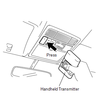
(a) To inspect the garage door opener system, press each switch and check that the LED in the "HomeLink" logo illuminates as illustrated. If one or more of the switches do not cause the LED to illuminate, confirm that the fuse and the wiring to the garage door opener system unit is normal. If the fuse and wiring are normal, and the LED does not illuminate, replace the garage door opener system unit located in the roof console box assembly. |
|
.png)
2. INSPECT GARAGE DOOR OPENER REGISTRATION AND TRANSMITTING
HINT:
Use the KENT-MOORE "HomeLink" tester, and the KENT-MOORE handheld transmitter for this test. First clear the customer's transmitter codes, and then register the code of the KENT-MOORE handheld transmitter to the garage door opener system.
|
(a) Check if the code of the KENT-MOORE handheld transmitter was successfully registered. HINT: If the code of the KENT-MOORE handheld transmitter cannot be registered, replace the garage door opener system unit. |
|
.png)
(b) Press the garage door opener switch that was used to copy the signal from the handheld transmitter. Check if the green LED of the "HomeLink" tester illuminates.
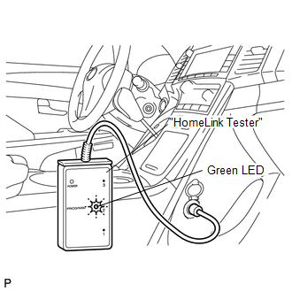
HINT:
If the green LED does not illuminate, replace the garage door opener system unit that is located in the roof console box assembly.
(c) When the inspection is complete, re-register the customer's handheld transmitter codes.
 System Description
SYSTEM DESCRIPTION
1. DESCRIPTION
(a) A maximum of 3 codes for transmitter-code based systems such as garage doors
gates and entry gates can be registered to the vehicle garage door opener system. ...

Other materials about Toyota Venza:
Diagnostic Trouble Code Chart
DIAGNOSTIC TROUBLE CODE CHART
HINT:
If a trouble code is displayed during the DTC check, inspect the trouble areas
listed below for that code. For details of the code, refer to the following "See
page".
Power back door system
DTC C ...
Installation
INSTALLATION
CAUTION / NOTICE / HINT
HINT:
Use the same procedure for the LH side and RH side.
The following procedure is for the LH side.
If the sensor rotor needs to be replaced, replace it together with the
rear drive shaft assembly. ...
Data List / Active Test
DATA LIST / ACTIVE TEST
1. DATA LIST
NOTICE:
In the table below, the values listed under "Normal Condition" are reference
values. Do not depend solely on these reference values when deciding whether a part
is faulty or not.
HINT:
Using the T ...

0.1181