Toyota Venza: Front Passenger Side Power Window Auto Up / Down Function does not Operate with Front Passenger Side Power Window Switch
DESCRIPTION
If the manual up/down function can be performed but the auto up/down function cannot, the fail-safe mode may be functioning.
If the power window initialization (See page
.gif) ) has not been performed, the auto up/down function
) has not been performed, the auto up/down function
will not operate.
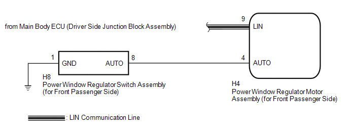
WIRING DIAGRAM
CAUTION / NOTICE / HINT
NOTICE:
- The power window control system uses a multiplex communication system
(LIN communication system). Inspect the communication function by following
How to Proceed with Troubleshooting (See page
). Troubleshoot the power window control
system after confirming that the communication system is functioning properly. - When the power window regulator motor assembly (for front passenger side) is reinstalled or replaced, the power window control system must be initialized.
- After a door glass or a door glass run has been replaced, the jam protection
function may operate unexpectedly when the auto up function is used. In
such cases, the auto up function can be reinitialized by repeating the following
operations at least 5 times:
- Close the power window by fully pulling up the power window regulator switch assembly (for front passenger side) and holding it at the auto up position.
- Open the power window by fully pushing down the power window regulator switch assembly (for front passenger side).
- When the ECU determines that the power window regulator motor assembly (for front passenger side) has a malfunction, DTC B2311 is set.
PROCEDURE
|
1. |
READ VALUE USING TECHSTREAM (P-Door Motor) |
(a) Connect the Techstream to the DLC3.
(b) Turn the ignition switch to ON.
(c) Turn the Techstream on.
(d) Enter the following menus: Body Electrical / P-Door Motor / Data List.
(e) Read the Data List according to the display on the Techstream.
P-Door Motor (Power Window Regulator Motor Assembly (for Front Passenger Side))|
Tester Display |
Measurement Item/Range |
Normal Condition |
Diagnostic Note |
|---|---|---|---|
|
P Door P/W Auto SW |
Front passenger side power window auto switch signal / ON or OFF |
ON: Front passenger door power window auto switch operated OFF: Front passenger door power window auto switch not operated |
- |
OK:
On the Techstream screen, ON or OFF is displayed accordingly.
| NG | .gif) |
GO TO STEP 4 |
|
.gif)
|
2. |
PERFORM INITIALIZATION (for Front Passenger Side) |
(a) Initialize the power window regulator motor assembly (for front passenger
side) (See page ).
|
|
3. |
CHECK POWER WINDOW CONTROL SYSTEM (AUTO UP/DOWN FUNCTION) |
(a) Check that the front passenger side door power window moves when the auto
up/down function of the power window regulator switch assembly (for front passenger
side) is operated (See page ).
OK:
Front passenger side auto up/down function is normal.
| OK | |
END (PROBLEM DUE TO INITIALIZATION FAILURE) |
| NG | |
REPLACE POWER WINDOW REGULATOR MOTOR ASSEMBLY (for Front Passenger Side) |
|
4. |
INSPECT POWER WINDOW REGULATOR SWITCH ASSEMBLY (for Front Passenger Side) |
|
(a) Remove the power window regulator switch assembly (for front passenger
side) (See page |
|
(b) Measure the resistance according to the value(s) in the table below.
Standard Resistance:
|
Tester Connection |
Condition |
Specified Condition |
|---|---|---|
|
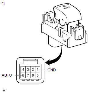
8 (AUTO) - 1 (GND) |
Auto up or auto down position |
Below 1 Ω |
|
*1 |
Component without harness connected (Power Window Regulator Switch Assembly (for Front Passenger Side)) |
| NG | |
REPLACE POWER WINDOW REGULATOR SWITCH ASSEMBLY (for Front Passenger Side) |
|
|
5. |
CHECK HARNESS AND CONNECTOR (POWER WINDOW SWITCH - REGULATOR MOTOR) |
|
(a) Disconnect the power window regulator motor assembly (for front passenger side) connector. |
|
(b) Measure the resistance according to the value(s) in the table below.
Standard Resistance:
|
Tester Connection |
Condition |
Specified Condition |
|---|---|---|
|
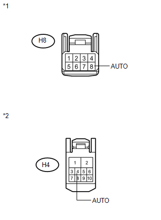
H8-8 (AUTO) - H4-4 (AUTO) |
Always |
Below 1 Ω |
|
H8-8 (AUTO) - Body ground |
Always |
10 kΩ or higher |
|
*1 |
Front view of wire harness connector (to Power Window Regulator Switch Assembly (for Front Passenger Side)) |
|
*2 |
Front view of wire harness connector (to Power Window Regulator Motor Assembly (for Front Passenger Side)) |
| OK | |
REPLACE POWER WINDOW REGULATOR MOTOR ASSEMBLY (for Front Passenger Side) |
| NG | |
REPAIR OR REPLACE HARNESS OR CONNECTOR |
 Driver Side Power Window Auto Up / Down Function does not Operate with Power
Window Master Switch
Driver Side Power Window Auto Up / Down Function does not Operate with Power
Window Master Switch
DESCRIPTION
If the manual up/down function can be performed but the auto up/down function
cannot, then the fail-safe mode may be functioning.
If the power window initialization (See page
) has n ...
 Rear Power Window LH Auto Up / Down Function does not Operate with Rear Power
Window Switch LH
Rear Power Window LH Auto Up / Down Function does not Operate with Rear Power
Window Switch LH
DESCRIPTION
If the manual up/down function can be performed but the auto up/down function
cannot, the fail-safe mode may be functioning.
If the power window initialization (See page
) has not be ...
Other materials about Toyota Venza:
Front Seat Inner Belt Assembly
Components
COMPONENTS
ILLUSTRATION
ILLUSTRATION
Inspection
INSPECTION
PROCEDURE
1. INSPECT FRONT SEAT INNER BELT ASSEMBLY LH (w/ Seat Position Memory System)
(a) Measure the resistance according to the value(s) in the table below.
...
System Description
SYSTEM DESCRIPTION
1. POWER DOOR LOCK CONTROL SYSTEM DESCRIPTION
(a) The power door lock system locks/unlocks all doors.
The door control switch sends "lock/unlock" request signals to the main body
ECU (driver side junction block assembly). Then ...
Precaution
PRECAUTION
CAUTION:
Replace any faulty seat belt components (outer belt, inner belt, bolts, nuts,
adjustable shoulder anchor, tether anchor hardware and other related parts). When
inspecting a vehicle that was in a collision, be sure to check all of the ...

0.1164