Toyota Venza: Inspection
INSPECTION
PROCEDURE
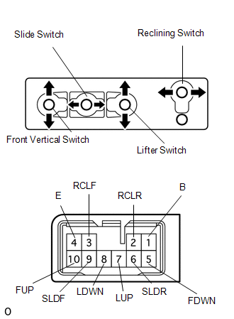
1. INSPECT FRONT POWER SEAT SWITCH LH (w/o Seat Position Memory System)
|
(a) Measure the resistance between the terminals when each switch is operated. Standard Resistance: Slide Switch
If the result is not as specified, replace the switch. |
|
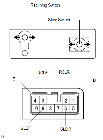
2. INSPECT FRONT POWER SEAT SWITCH RH (w/o Seat Position Memory System)
|
(a) Measure the resistance between the terminals when each switch is operated. Standard Resistance: Slide Switch
If the result is not as specified, replace the switch. |
|
 Removal
REMOVAL
PROCEDURE
1. REMOVE FRONT SEAT HEADREST ASSEMBLY
2. REMOVE FRONT SEAT REAR OUTER TRACK COVER
3. REMOVE FRONT SEAT REAR INNER TRACK COVER
4. REMOVE FRONT SEAT ASSEMBLY
5. REMOVE ...
 Installation
INSTALLATION
PROCEDURE
1. INSTALL POWER SEAT SWITCH
(a) Install the power seat switch with the 3 screws.
(b) Connect the connector.
2. IN ...
Other materials about Toyota Venza:
Installation
INSTALLATION
PROCEDURE
1. INSTALL THERMOSTAT
(a) Install a new gasket to the thermostat.
(b) Install the thermostat with the jiggle valve facing upward.
HINT:
The jiggle valve may be set to within 10° on either side of the prescribed
...
Cleaning and protecting the vehicle interior
The following procedures will help protect your vehicle’s interior and keep
it in top condition: - Protecting the vehicle interior
Remove dirt and dust using a vacuum cleaner. Wipe dirty surfaces with a cloth dampened
with lukewarm water.
- Cleaning t ...
Problem Symptoms Table
PROBLEM SYMPTOMS TABLE
Use the table below to help determine the cause of problem symptoms.
If multiple suspected areas are listed, the potential causes of the symptoms
are listed in order of probability in the "Suspected Area" column ...

0.1557