Toyota Venza: Front Seat Inner Belt Assembly
Components
COMPONENTS
ILLUSTRATION
ILLUSTRATION
Inspection
INSPECTION
PROCEDURE
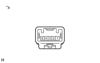
1. INSPECT FRONT SEAT INNER BELT ASSEMBLY LH (w/ Seat Position Memory System)
|
(a) Measure the resistance according to the value(s) in the table below. Standard Resistance:
If the result is not as specified, replace the front seat inner belt assembly LH. |
|
Removal
REMOVAL
PROCEDURE
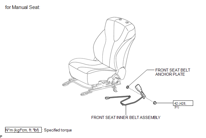
1. REMOVE FRONT SEAT ASSEMBLY (for Manual Seat)
(See page .gif) )
)
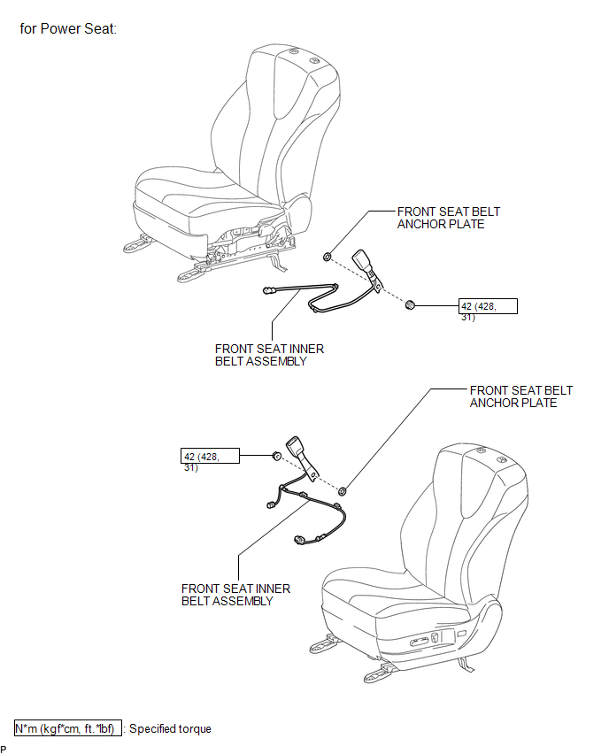
2. REMOVE FRONT SEAT ASSEMBLY (for Power Seat)
(See page )
3. REMOVE FRONT SEAT INNER BELT ASSEMBLY (for Manual Seat)
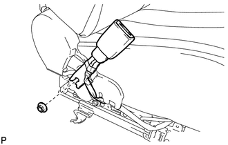
(a) Disconnect the connector and disengage each clamp.
|
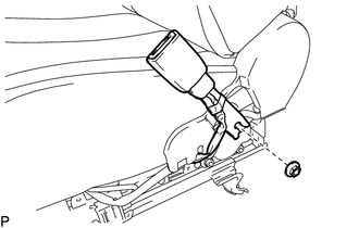
(b) Remove the nut and front seat inner belt assembly. |
|
4. REMOVE FRONT SEAT INNER BELT ASSEMBLY (for Power Seat)
(a) Disconnect each connector and disengage each clamp.
|
(b) Remove the nut and front seat inner belt assembly. |
|
5. REMOVE FRONT SEAT BELT ANCHOR PLATE
(a) Remove the front seat belt anchor plate.
Installation
INSTALLATION
PROCEDURE
1. INSTALL FRONT SEAT BELT ANCHOR PLATE
(a) Install the front seat belt anchor plate.
2. INSTALL FRONT SEAT INNER BELT ASSEMBLY (for Manual Seat)
|
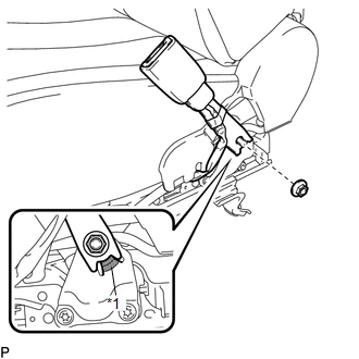
(a) Install the front seat inner belt assembly with the nut. Text in Illustration
Torque: 42 N·m {428 kgf·cm, 31 ft·lbf} NOTICE: Do not allow the anchor part of the front seat inner belt assembly to overlap the protruding part of the front seat adjuster. |
|
(b) Connect the connector and engage each clamp.
3. INSTALL FRONT SEAT INNER BELT ASSEMBLY (for Power Seat)
|
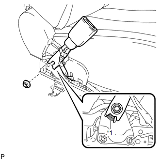
(a) Install the front seat inner belt assembly with the nut. Text in Illustration
Torque: 42 N·m {428 kgf·cm, 31 ft·lbf} NOTICE: Do not allow the anchor part of the front seat inner belt assembly to overlap the protruding part of the front seat adjuster. |
|
(b) Connect each connector and engage each clamp.
4. INSTALL FRONT SEAT ASSEMBLY (for Manual Seat)
(See page .gif) )
)
5. INSTALL FRONT SEAT ASSEMBLY (for Power Seat)
(See page )
 Front Passenger Seat Belt Warning Light
Components
COMPONENTS
ILLUSTRATION
Installation
INSTALLATION
PROCEDURE
1. INSTALL ACCESSORY METER ASSEMBLY (w/o Rear View Monitor System)
(a) Connect the connector.
(b) Engage the 2 clam ...

Other materials about Toyota Venza:
Pressure Control Solenoid "C" Performance (Shift Solenoid Valve SL3) (P0796)
SYSTEM DESCRIPTION
The TCM uses the vehicle speed signal and signals from the transmission speed
sensors (NC, NT) to detect the actual gear (1st, 2nd, 3rd, 4th, 5th or 6th gear).
Then the TCM compares the actual gear with the shift schedule in the TCM memo ...
How To Proceed With Troubleshooting
CAUTION / NOTICE / HINT
HINT:
Use the following procedure to troubleshoot the wiper and washer system.
PROCEDURE
1.
VEHICLE BROUGHT TO WORKSHOP
NEXT
...
Sound Quality is Bad Only when CD is Played (Volume is Too Low)
PROCEDURE
1.
REPLACE CD AND RECHECK
(a) Replace the CD with a known good one and check that the malfunction disappears.
OK:
Malfunction disappears.
OK
END
NG
REPLACE RADIO AN ...

0.1357