Toyota Venza: Fog light switch
The fog lights improve visibility in difficult driving conditions, such as in rain or fog. The fog lights can be used when the headlights are on low beam.
Type A
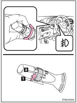
1.  Off
Off
2.  On
On
Type B
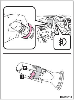
1.  Off
Off
2.  On
On
Wiper intervals can be adjusted for intermittent operation (when
 or
or
 is selected).
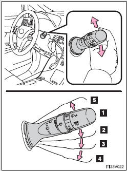
Type A
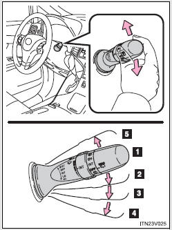
1.  Off
Off
2.  Intermittent wiper operation
3.  Low speed wiper operation
4.  High speed wiper operation
5.  Temporary operation
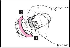
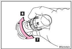
6. Increases the intermittent windshield wiper frequency
7. Decreases the intermittent windshield wiper frequency
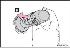
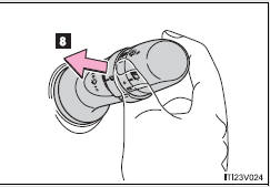
8. Wash/wipe operation
Wipers operate automatically.
Type B
1.  Off
Off
2.  Intermittent wiper operation
3.  Low speed wiper operation
4.  High speed wiper operation
5.  Temporary operation
6. Increases the intermittent windshield wiper frequency
7. Decreases the intermittent windshield wiper frequency
8. Wash/wipe operation
Wipers operate automatically.
- The windshield wiper and washer can be operated when
►Vehicles with smart key system The “ENGINE START STOP” switch is in IGNITION ON mode.
► Vehicles without smart key system The engine switch is in the “ON” position.
- If no windshield washer fluid sprays
Check that the washer nozzles are not blocked if there is washer fluid in the windshield washer fluid reservoir.
CAUTION
- Caution regarding the use of washer fluid
When it is cold, do not use the washer fluid until the windshield becomes warm. The fluid may freeze on the windshield and cause low visibility. This may lead to an accident, resulting in death or serious injury.
NOTICE
- When the windshield is dry
Do not use the wipers, as they may damage the windshield.
- When there is no washer fluid spray from the nozzle
Damage to the washer fluid pump may be caused if the lever is pulled toward you and held continually.
- When a nozzle becomes blocked
Do not try to clear it with a pin or other object. The nozzle will be damaged.
 Automatic High Beam
The Automatic High Beam uses an in-vehicle camera sensor to assess the brightness
of streetlights, the lights of oncoming and preceding vehicles, etc., and automatically
turns high beam on or off ...
 Rear window wiper and washer
Type A
1. Off
2. Intermittent window wiper operation
3. Normal window wiper operation
4. Washer/wiper dual operation
5. Washer/wiper dual operation
Type B
1. Off
2. Intermittent win ...
Other materials about Toyota Venza:
How To Proceed With Troubleshooting
CAUTION / NOTICE / HINT
HINT:
The wireless door lock control system troubleshooting procedures are
based on the premise that the power door lock control system is operating
normally. Check the power door lock control system first before troub ...
Parking Brake System
Problem Symptoms Table
PROBLEM SYMPTOMS TABLE
HINT:
Use the table below to help determine the cause of problem symptoms. If multiple
suspected areas are listed, the potential causes of the symptoms are listed in order
of probability in the "Suspe ...
CD cannot be Ejected
PROCEDURE
1.
CHECK OPERATION
(a) Press the disc eject switch of the radio and display receiver assembly for
5 seconds or more and check that the CD is ejected.
OK:
CD is ejected.
NG
REPLACE RADIO AND D ...

0.1602