Toyota Venza: Antenna Coil Open / Short (B2784)
DESCRIPTION
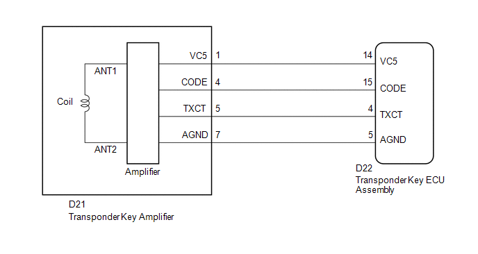
The transponder key coil is built into the transponder key amplifier and receives a key code signal from the transponder chip in the key. This signal is amplified by the amplifier, then it is output to the transponder key ECU assembly.
|
DTC No. |
DTC Detection Condition |
Trouble Area |
|---|---|---|
|
B2784 |
Antenna coil is open/shorted. |
|
WIRING DIAGRAM
CAUTION / NOTICE / HINT
NOTICE:
If the transponder key ECU assembly is replaced, register the key and ECU communication
ID (See page .gif) ).
).
PROCEDURE
|
1. |
READ VALUE USING TECHSTREAM |
(a) Connect the Techstream to the DLC3.
(b) Turn the ignition switch to ON.
(c) Turn the Techstream on.
(d) Enter the following menus: Body Electrical / Immobiliser / Data List.
(e) Read the Data List according to the display on the Techstream.
Immobiliser (Transponder Key ECU Assembly)|
Tester Display |
Measurement Item/Range |
Normal Condition |
Diagnostic Note |
|---|---|---|---|
|
Antenna Coil Status |
Transponder key amplifier coil condition/Normal or Fail |
Normal: Antenna coil normal Fail: Antenna coil malfunctioning |
- |
OK:
On the Techstream screen, the item displays Normal according to the chart above.
| OK | .gif) |
REPLACE TRANSPONDER KEY ECU ASSEMBLY |
|
.gif)
|
2. |
CHECK HARNESS AND CONNECTOR (TRANSPONDER KEY ECU - TRANSPONDER KEY AMPLIFIER) |
(a) Disconnect the transponder key ECU assembly connector.
|
(b) Disconnect the transponder key amplifier connector. |
|
(c) Measure the resistance according to the value(s) in the table below.
Standard Resistance:
|
Tester Connection |
Condition |
Specified Condition |
|---|---|---|
|
D22-4 (TXCT) - D21-5 (TXCT) |
Always |
Below 1 Ω |
|
D22-5 (AGND) - D21-7 (AGND) |
Always |
Below 1 Ω |
|
D22-14 (VC5) - D21-1 (VC5) |
Always |
Below 1 Ω |
|
D22-15 (CODE) - D21-4 (CODE) |
Always |
Below 1 Ω |
|
D22-4 (TXCT) - Body ground |
Always |
10 kΩ or higher |
|
D22-5 (AGND) - Body ground |
Always |
10 kΩ or higher |
|
D22-14 (VC5) - Body ground |
Always |
10 kΩ or higher |
|
D22-15 (CODE) - Body ground |
Always |
10 kΩ or higher |
|
D21-5 (TXCT) - Body ground |
Always |
10 kΩ or higher |
|
D21-7 (AGND) - Body ground |
Always |
10 kΩ or higher |
|
D21-1 (VC5) - Body ground |
Always |
10 kΩ or higher |
|
D21-4 (CODE) - Body ground |
Always |
10 kΩ or higher |
|
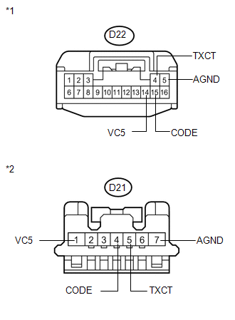
*1 |
Front view of wire harness connector (to Transponder Key ECU Assembly) |
|
*2 |
Front view of wire harness connector (to Transponder Key Amplifier) |
| NG | |
REPAIR OR REPLACE HARNESS OR CONNECTOR |
|
|
3. |
INSPECT TRANSPONDER KEY AMPLIFIER (POWER SOURCE AND GROUND) |
(a) Reconnect the transponder key ECU assembly connector.
|
(b) Reconnect the transponder key amplifier connector. |
|
(c) Measure the voltage and resistance according to the value(s) in the table below.
Standard Voltage:
|
Tester Connection |
Condition |
Specified Condition |
|---|---|---|
|
D22-14 (VC5) - Body ground |
No key is in ignition key cylinder |
Below 1 V |
|
D22-14 (VC5) - Body ground |
Key is in ignition key cylinder |
4.6 to 5.4 V |
Standard Resistance:
|
Tester Connection |
Condition |
Specified Condition |
|---|---|---|
|
D22-5 (AGND) - Body ground |
Always |
Below 1 Ω |
|
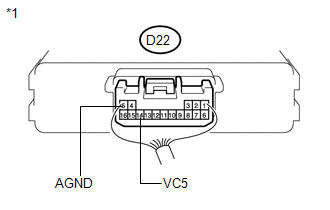
*1 |
Component with harness connected (Transponder Key ECU Assembly) |
| OK | |
REPLACE TRANSPONDER KEY AMPLIFIER |
| NG | |
REPLACE TRANSPONDER KEY ECU ASSEMBLY |
 Push Switch / Key Unlock Warning Switch Malfunction (B2780)
DESCRIPTION
This DTC is stored if the transponder key ECU assembly does not detect that the
unlock warning switch assembly is ON even when the ignition switch is ON. Under
normal conditions, the ...
 Transponder Chip Malfunction (B2793)
DESCRIPTION
This DTC is stored when a malfunction is found in the key during key code registration
or a key code is not registered normally. Replace the key if the key code registration
is not pe ...
Other materials about Toyota Venza:
Installation
INSTALLATION
PROCEDURE
1. INSTALL BRAKE MASTER CYLINDER SUB-ASSEMBLY
NOTICE:
When install a new brake master cylinder sub-assembly, remove the protectors
from the piston and outlet ports.
(a) Install a new O-ring to the brake master cylinder sub-assembl ...
Transponder Key Ecu
Components
COMPONENTS
ILLUSTRATION
Removal
REMOVAL
PROCEDURE
1. REMOVE AIR CONDITIONING UNIT ASSEMBLY
HINT:
Refer to the procedure up to Remove Air Conditioning Unit Assembly (See page
).
2. REMOVE TRANSPONDER KEY ECU ASSEMBLY
(a) ...
Operation Check
OPERATION CHECK
1. CHECK BASIC FUNCTIONS
(a) When the back door is partially closed, check that the motor operates to
fully close (lock) the back door.
(b) Check that the back door can be opened.
(c) When the back door is partially closed and then the mo ...

0.1373