Toyota Venza: Installation
INSTALLATION
PROCEDURE
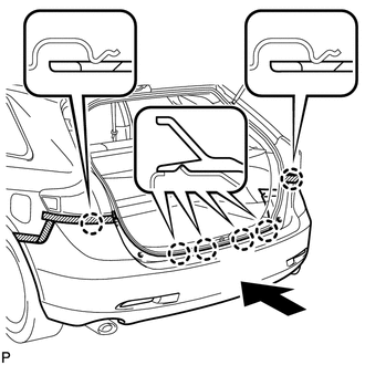
1. INSTALL REAR BUMPER ASSEMBLY
(a) w/ Intuitive Parking Assist System:
(1) Connect each connector.
|
(b) Engage the 6 claws and install the rear bumper assembly as shown in the illustration. |
|
|
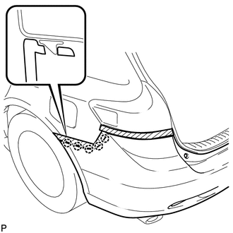
(c) Engage the 5 claws. HINT: Use the same procedure for the RH side and LH side. |
|
|
(d) Install the screw. HINT: Use the same procedure for the RH side and LH side. |
|
.png)
|
(e) Engage the 2 clips and install the 2 screws. |
|
.png)
|
(f) Install the 2 bolts and 2 screws. Torque: Bolt : 5.5 N·m {56 kgf·cm, 49 in·lbf} |
|
.png)
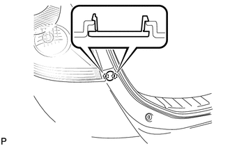
(g) Engage the 2 clips.
2. INSTALL REAR BUMPER PLATE LH
|
(a) Engage the 2 claws and install the rear bumper plate LH. |
|
3. INSTALL REAR BUMPER PLATE RH
HINT:
Use the same procedure for the RH side and LH side.
 Disassembly
DISASSEMBLY
PROCEDURE
1. REMOVE ULTRASONIC SENSOR CLIP (w/ Intuitive Parking Assist System)
2. REMOVE NO. 1 ULTRASONIC SENSOR (w/ Intuitive Parking Assist System)
3. REMOVE NO. 1 ULTRASONIC ...
 Reassembly
REASSEMBLY
PROCEDURE
1. INSTALL NO. 1 REAR BUMPER REINFORCEMENT
(a) Install the No. 1 rear bumper reinforcement with the 6 nuts.
Torque:
68 N·m {693 kgf·cm, 50 ft·lbf}
...
Other materials about Toyota Venza:
CD Sound Skips
PROCEDURE
1.
CHECK CD
(a) Check that the CD is not deformed or cracked.
OK:
No deformation or cracks on the CD
NG
END (CD IS FAULTY)
...
On-vehicle Inspection
ON-VEHICLE INSPECTION
PROCEDURE
1. CHECK THROTTLE BODY ASSEMBLY
(a) Check the throttle control motor operating sounds.
(1) Turn the ignition switch to ON.
(2) When pressing the accelerator pedal, check the operating sound of the running
motor. Make sure ...
Reassembly
REASSEMBLY
PROCEDURE
1. INSTALL SHIFT LOCK CONTROL COMPUTER SUB-ASSEMBLY
(a) Engage the 3 claws to install the shift lock control computer sub-assembly.
(b) Connect the connector.
2. INSTALL LOWER ...

0.1218