Toyota Venza: Installation
INSTALLATION
PROCEDURE
1. INSTALL SEPARATE TYPE FRONT SEAT CUSHION COVER
|
(a) Using a tacker, install the separate type front seat cushion heater to the end of the separate type front seat cushion cover with 25 new tack pins. NOTICE: Be careful not to damage the cushion. |
|
.png)
|
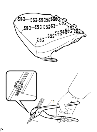
(b) Using hog ring pliers, temporarily install the separate type front seat cover with 18 new hog rings. Text in Illustration
NOTICE:
|
|
2. INSTALL SEPARATE TYPE FRONT SEAT CUSHION COVER WITH PAD
.gif)
3. INSTALL POWER SEAT SWITCH
4. INSTALL FRONT INNER SEAT CUSHION SHIELD
5. INSTALL FRONT SEAT INNER BELT ASSEMBLY
6. INSTALL FRONT SEAT CUSHION SHIELD ASSEMBLY
7. INSTALL SLIDE AND VERTICAL POWER SEAT SWITCH KNOB
8. INSTALL RECLINING POWER SEAT SWITCH KNOB
9. INSTALL FRONT SEAT ASSEMBLY
10. INSTALL FRONT SEAT REAR INNER TRACK COVER
11. INSTALL FRONT SEAT REAR OUTER TRACK COVER
12. INSTALL FRONT SEAT HEADREST ASSEMBLY
13. INSPECT FRONT SEAT ASSEMBLY
14. INSPECT SRS WARNING LIGHT
(See page )
 Inspection
INSPECTION
PROCEDURE
1. INSPECT FRONT SEAT CUSHION HEATER LH
(a) Check the seat cushion heater.
(1) Apply battery voltage and check the seat cushion heater.
OK:
...

Other materials about Toyota Venza:
Sending Malfunction (Navigation to APGS) (U0073,U0100,U0140,U0155)
DESCRIPTION
These DTCs are stored when a malfunction occurs in the CAN communication circuit.
DTC No.
DTC Detection Condition
Trouble Area
U0073
CAN bus connection error
CAN communicatio ...
Automatic anti-glare function
Responding to the level of brightness of the headlights of vehicles behind, the
reflected light is automatically reduced.
Changing automatic anti-glare function mode ON/OFF
When the automatic anti-glare function is in ON mode, the indicator illuminates.
...
On-vehicle Inspection
ON-VEHICLE INSPECTION
PROCEDURE
1. INSPECT REAR COMBINATION LIGHT ASSEMBLY
(a) Disconnect the connector from the rear combination light assembly.
(b) Measure the voltage according to the value(s) in ...

0.1562