Toyota Venza: Removal
REMOVAL
PROCEDURE
1. REMOVE AUTOMATIC TRANSAXLE ASSEMBLY (for 2WD)
When Not Using the Engine Support Bridge: (See page
.gif) )
)
When Using the Engine Support Bridge: (See page
)
2. REMOVE AUTOMATIC TRANSAXLE ASSEMBLY (for AWD)
When Not Using the Engine Support Bridge: (See page
)
When Using the Engine Support Bridge: (See page
)
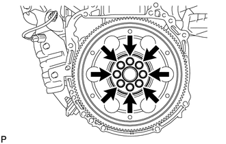
3. REMOVE DRIVE PLATE AND RING GEAR SUB-ASSEMBLY
|
(a) Using SST, hold the crankshaft pulley. SST: 09213-54015 SST: 09330-00021 HINT: Part number of installation bolt for SST (crankshaft pulley holding tool): 91551-80650 (quantity: 2) |
|
.png)
|
(b) Remove the 8 bolts, front drive plate spacer, drive plate and ring gear sub-assembly, and rear drive plate spacer. |
|
4. REMOVE REAR ENGINE OIL SEAL
|
(a) Using a knife, cut off the lip of the oil seal. Text in Illustration
|
|
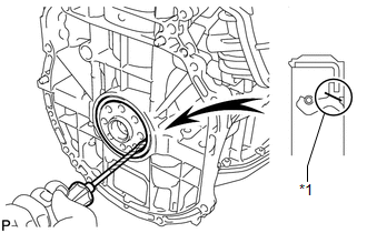
(b) Using a screwdriver, pry out the oil seal.
HINT:
Tape the screwdriver tip before use.
NOTICE:
Do not damage the surface of the oil seal press fit hole or the crankshaft.
 Components
COMPONENTS
ILLUSTRATION
...
 Installation
INSTALLATION
PROCEDURE
1. INSTALL REAR ENGINE OIL SEAL
(a) Apply MP grease to the lip of a new oil seal.
NOTICE:
Do not allow foreign matter to contact the lip of the oil seal.
Do not ...
Other materials about Toyota Venza:
Driver Side Solar Sensor Short Circuit (B14A2)
DESCRIPTION
The solar sensor is installed on the upper side of the instrument panel. It detects
sunlight to control air conditioning AUTO mode. The output voltage from the solar
sensor varies in accordance with the amount of sunlight. When the amount of ...
Removal
REMOVAL
PROCEDURE
1. REMOVE UPPER CONSOLE PANEL SUB-ASSEMBLY (w/o Seat Heater System)
2. REMOVE UPPER CONSOLE PANEL SUB-ASSEMBLY (w/ Seat Heater System)
3. REMOVE NO. 2 CONSOLE BOX CARPET
4. REMOVE CONSOLE BOX ASSEMBLY
5. REMOVE AIR CONDITION ...
Problem Symptoms Table
PROBLEM SYMPTOMS TABLE
HINT:
Use the table below to help determine the cause of problem symptoms.
If multiple suspected areas are listed, the potential causes of the symptoms
are listed in order of probability in the "Suspected Area" ...

0.1699