Toyota Venza: Inspection
INSPECTION
PROCEDURE
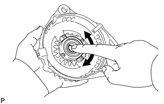
1. INSPECT GENERATOR PULLEY WITH CLUTCH
|
(a) Hold the center of the pulley, and confirm that the outer ring turns counterclockwise and does not turn clockwise. Text in Illustration
If the result is not as specified, replace the generator pulley with clutch. |
|

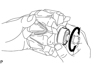
2. INSPECT GENERATOR DRIVE END FRAME BEARING
|
(a) Check that the bearing is not rough or worn and that it rotates smoothly. OK: The bearing rotates smoothly. If the bearing does not rotate smoothly, replace the bearing. |
|
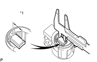
3. INSPECT GENERATOR BRUSH HOLDER ASSEMBLY
|
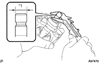
(a) Using a vernier caliper, measure the brush length. Text in Illustration
Standard length: 9.5 to 11.5 mm (0.374 to 0.453 in.) Minimum length: 4.5 mm (0.177 in.) If the brush length is less than the minimum, replace the generator brush holder assembly. |
|
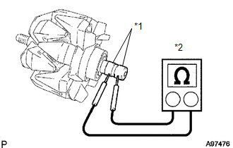
4. INSPECT GENERATOR ROTOR ASSEMBLY
|
(a) Check that the generator rotor bearing is not rough or worn. If the result is not as specified, replace the generator rotor assembly. |
|
|
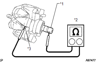
(b) Check the rotor for an open circuit. Text in Illustration
(1) Measure the resistance according to the value(s) in the table below. Standard Resistance:
If the result is not as specified, replace the generator rotor assembly. |
|
|
(c) Check if the rotor is grounded. Text in Illustration
(1) Measure the resistance according to the value(s) in the table below. Standard Resistance:
If the result is not as specified, replace the generator rotor assembly. |
|
(d) Check the slip ring diameter.
|
(1) Using a vernier caliper, measure the diameter of each slip ring. Text in Illustration
Standard diameter: 14.2 to 14.4 mm (0.559 to 0.567 in.) Minimum diameter: 14 mm (0.551 in.) If the diameter is less than the minimum, replace the generator rotor assembly. |
|
 Disassembly
DISASSEMBLY
PROCEDURE
1. REMOVE GENERATOR PULLEY CAP
(a) Using a screwdriver, puncture the center of the generator pulley
cap and pry it off.
NOTICE:
Do not reuse the generator ...
 Reassembly
REASSEMBLY
PROCEDURE
1. INSTALL GENERATOR ROTOR ASSEMBLY
(a) Place the generator drive end frame on the generator pulley.
(b) Install the ...
Other materials about Toyota Venza:
Power Source Circuit
DESCRIPTION
1. w/o Multi-information Display
(a) This circuit is the power source circuit for the accessory meter assembly.
This circuit provides two types of power sources; one is a constant power source
mainly used as a backup power source, and the oth ...
Tire size
- Typical tire size information
The illustration indicates typical tire size.
1. Tire use
(P = Passenger car, T = Temporary use)
2. Section width (millimeters)
3. Aspect ratio
(tire height to section width)
4. Tire construction code
(R = Radial ...
Removal
REMOVAL
CAUTION / NOTICE / HINT
HINT:
The front side fix window assembly can be reused. When installing the
window, if any of the clips on the quarter window glass are broken, butyl
tape can be used to support the glass until the applied adh ...

0.161