Toyota Venza: SRS Warning Light Remains ON
DESCRIPTION
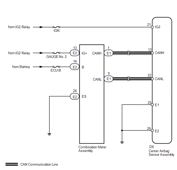
The SRS warning light is located on the combination meter assembly.
When the SRS is normal, the SRS warning light comes on for approximately 6 seconds after the ignition switch is turned from off to ON, and then goes off automatically.
If there is a malfunction in the SRS, the SRS warning light comes on to inform the driver of a problem.
When terminals TC and CG of the DLC3 are connected, the DTC is displayed by blinking of the SRS warning light.
The SRS is equipped with a voltage-increase circuit (DC-DC converter) in the center airbag sensor assembly in case the source voltage drops.
When the battery voltage drops, the voltage-increase circuit (DC-DC converter) functions to increase the voltage of the SRS to normal voltage.
A malfunction in this circuit is not recorded in the center airbag sensor assembly. The SRS warning light automatically goes off when the source voltage returns to normal.
The signal to illuminate the SRS warning light is transmitted from the center airbag sensor assembly to the combination meter assembly through the CAN communication system and multiplex communication system.
WIRING DIAGRAM
PROCEDURE
|
1. |
CHECK SRS WARNING LIGHT OPERATION |
(a) Check the SRS warning light operation approximately 6 seconds after the ignition switch is turned to ON.
|
SRS Warning Light Illumination |
Proceed to |
|---|---|
|
Remains on |
A |
|
Remains on after it goes off |
B |
| B | .gif) |
GO TO STEP 6 |
|
.gif)
|
2. |
CHECK BATTERY VOLTAGE |
(a) Measure the voltage of the battery.
Standard Voltage:
11 to 14 V
Result|
Result |
Proceed to |
|---|---|
|
OK |
A |
|
NG (for 2GR-FE) |
B |
|
NG (for 1AR-FE) |
C |
| B | |
INSPECT CHARGING SYSTEM AND BATTERY |
| C | |
INSPECT CHARGING SYSTEM AND BATTERY |
|
|
3. |
CHECK CONNECTOR |
(a) Turn the ignition switch off.
(b) Disconnect the cable from the negative (-) battery terminal, and wait for at least 90 seconds.
(c) Check that the connector is properly connected to the center airbag sensor assembly.
OK:
The connector is properly connected.
HINT:
If the connector is not connected securely, reconnect the connector and proceed to the next inspection.
(d) Disconnect the connector from the center airbag sensor assembly.
(e) Check that the terminal of the connector is not damaged.
OK:
The terminal is not deformed or damaged.
| NG | |
REPLACE WIRE HARNESS |
|
|
4. |
CHECK WIRE HARNESS (CENTER AIRBAG SENSOR ASSEMBLY - BODY GROUND) |
|
(a) Connect the cable to the negative (-) battery terminal. |
|
(b) Turn the ignition switch to ON.
(c) Operate all components of the electrical system (defogger, wipers, headlights, heater blower, etc.).
(d) Measure the voltage according to the value(s) in the table below.
Standard Voltage:
|
Tester Connection |
Switch Condition |
Specified Condition |
|---|---|---|
|
D6-21 (IG2) - Body ground |
Ignition switch ON |
8 to 16 V |
(e) Turn the ignition switch off.
(f) Measure the resistance according to the value(s) in the table below.
Standard Resistance:
|
Tester Connection |
Condition |
Specified Condition |
|---|---|---|
|
D6-25 (E1) - Body ground |
Always |
Below 1 Ω |
|
D6-26 (E2) - Body ground |
Always |
Below 1 Ω |
|
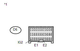
*1 |
Front view of wire harness connector (to Center Airbag Sensor Assembly) |
| NG | |
REPLACE WIRE HARNESS |
|
|
5. |
CHECK SRS WARNING LIGHT |
(a) Turn the ignition switch to ON.
(b) Check the SRS warning light condition.
OK:
After the primary check period, the SRS warning light goes off for approximately 10 seconds and remains on.
HINT:
The primary check period is approximately 6 seconds after the ignition switch is turned to ON.
| OK | |
REPLACE CENTER AIRBAG SENSOR ASSEMBLY |
| NG | |
REPLACE COMBINATION METER ASSEMBLY |
|
6. |
CHECK CAN COMMUNICATION SYSTEM |
(a) Use the Techstream to check if the CAN communication system is functioning normally.
HINT:
- Refer to Bus Check for the CAN communication system (See page
.gif) ).
). - The center airbag sensor assembly is connected to the CAN communication system. Therefore, before starting troubleshooting, make sure to check that there is no trouble in the CAN communication system.
|
Result |
Proceed to |
|---|---|
|
DTC is not output |
A |
|
DTC is output |
B |
| B | |
GO TO CAN COMMUNICATION SYSTEM |
|
|
7. |
CHECK BATTERY VOLTAGE |
(a) Measure the voltage of the battery.
Standard Voltage:
11 to 14 V
Result|
Result |
Proceed to |
|---|---|
|
OK |
A |
|
NG (for 2GR-FE) |
B |
|
NG (for 1AR-FE) |
C |
| B | |
INSPECT CHARGING SYSTEM AND BATTERY |
| C | |
INSPECT CHARGING SYSTEM AND BATTERY |
|
|
8. |
CHECK CONNECTOR |
(a) Turn the ignition switch off.
(b) Disconnect the cable from the negative (-) battery terminal, and wait for at least 90 seconds.
(c) Check that the connector is properly connected to the center airbag sensor assembly.
OK:
The connector is properly connected.
HINT:
If the connector is not connected securely, reconnect the connector and proceed to the next inspection.
(d) Disconnect the connector from the center airbag sensor assembly.
(e) Check that the terminal of the connector is not damaged.
OK:
The terminal is not deformed or damaged.
| NG | |
REPLACE WIRE HARNESS |
|
|
9. |
CHECK WIRE HARNESS (CENTER AIRBAG SENSOR ASSEMBLY - BODY GROUND) |
|
(a) Connect the cable to the negative (-) battery terminal. |
|
(b) Turn the ignition switch to ON.
(c) Operate all components of the electrical system (defogger, wipers, headlights, heater blower, etc.).
(d) Measure the voltage according to the value(s) in the table below.
Standard Voltage:
|
Tester Connection |
Switch Condition |
Specified Condition |
|---|---|---|
|
D6-21 (IG2) - Body ground |
Ignition switch ON |
8 to 16 V |
(e) Turn the ignition switch off.
(f) Measure the resistance according to the value(s) in the table below.
Standard Resistance:
|
Tester Connection |
Condition |
Specified Condition |
|---|---|---|
|
D6-25 (E1) - Body ground |
Always |
Below 1 Ω |
|
D6-26 (E2) - Body ground |
Always |
Below 1 Ω |
|
*1 |
Front view of wire harness connector (to Center Airbag Sensor Assembly) |
| NG | |
REPLACE WIRE HARNESS |
|
|
10. |
CHECK CONNECTOR |
(a) Disconnect the cable from the negative (-) battery terminal, and wait for at least 90 seconds.
(b) Check that the connector is properly connected to the combination meter assembly.
OK:
The connector is properly connected.
HINT:
If the connector is not connected securely, reconnect the connector and proceed to the next inspection.
(c) Disconnect the connector from the combination meter assembly.
(d) Check that the terminal of the connector is not damaged.
OK:
The terminal is not deformed or damaged.
| NG | |
REPLACE WIRE HARNESS |
|
|
11. |
CHECK WIRE HARNESS (COMBINATION METER ASSEMBLY - BODY GROUND) |
|
(a) Connect the cable to the negative (-) battery terminal. |
|
(b) Turn the ignition switch to ON.
(c) Measure the voltage according to the value(s) in the table below.
Standard Voltage:
|
Tester Connection |
Condition |
Specified Condition |
|---|---|---|
|
E2-14 (B) - Body ground |
Always |
11 to 14 V |
|
E2-13 (IG+) - Body ground |
Ignition switch ON |
11 to 14 V |
(d) Turn the ignition switch off.
(e) Measure the resistance according to the value(s) in the table below.
Standard Resistance:
|
Tester Connection |
Condition |
Specified Condition |
|---|---|---|
|
E2-24 (ES) - Body ground |
Always |
Below 1 Ω |
|
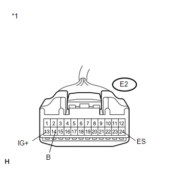
*1 |
Front view of wire harness connector (to Combination Meter Assembly) |
| NG | |
REPLACE WIRE HARNESS |
|
|
12. |
CHECK SRS WARNING LIGHT |
(a) Disconnect the cable from the negative (-) battery terminal, and wait for at least 90 seconds.
(b) Connect the connector to the combination meter assembly.
(c) Connect the cable to the negative (-) battery terminal.
(d) Turn the ignition switch to ON.
(e) Check the SRS warning light condition.
OK:
After the primary check period, the SRS warning light goes off for approximately 10 seconds and remains on.
HINT:
The primary check period is approximately 6 seconds after the ignition switch is turned to ON.
| OK | |
REPLACE CENTER AIRBAG SENSOR ASSEMBLY |
| NG | |
REPLACE COMBINATION METER ASSEMBLY |
 Front Airbag Sensor RH Malfunction (B1610/13)
DESCRIPTION
The front airbag sensor RH circuit consists of the center airbag sensor assembly
and front airbag sensor RH.
The front airbag sensor RH detects impacts to the vehicle and sends signals ...
 SRS Warning Light does not Come ON
DESCRIPTION
The SRS warning light is located on the combination meter assembly.
When the SRS is normal, the SRS warning light comes on for approximately 6 seconds
after the ignition switch is turn ...
Other materials about Toyota Venza:
Jam Protection Function does not Operate
DESCRIPTION
This symptom may occur for any of the windows.
The jam protection function operates within a specified range during the manual
up or auto up operation.
CAUTION / NOTICE / HINT
NOTICE:
The power window control system uses a multiplex ...
Removal
REMOVAL
PROCEDURE
1. REMOVE BACK DOOR PANEL TRIM ASSEMBLY
2. REMOVE REAR WIPER ARM HEAD CAP
(a) Disengage the 4 claws and remove the rear wiper arm head cap as shown
in the illustration.
3. ...
Short in GPS Antenna (B15C0,B15C1)
DESCRIPTION
These DTCs are stored when a malfunction occurs in the navigation antenna assembly.
DTC No.
DTC Detection Condition
Trouble Area
B15C0
Navigation antenna malfunction
...

0.1497