Toyota Venza: Disassembly
DISASSEMBLY
PROCEDURE
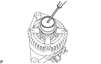
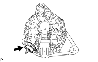
1. REMOVE GENERATOR PULLEY CAP
|
(a) Using a screwdriver, puncture the center of the generator pulley cap and pry it off. NOTICE: Do not reuse the generator pulley cap. |
|
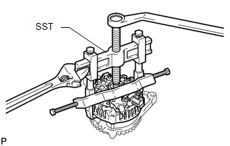
2. REMOVE GENERATOR PULLEY WITH CLUTCH
|
(a) Mount the generator in a vise. Text in Illustration
|
|
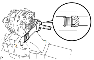
(b) Install SST (A) and (B) to the pulley as shown in the illustration.
SST: 09820-63021
|
(c) Use a wrench to hold SST (A), and turn SST (B) counterclockwise to loosen the generator pulley. Text in Illustration
NOTICE:
|
|
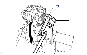
(d) Remove the generator pulley.
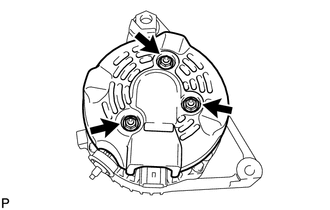
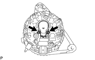
3. REMOVE GENERATOR REAR END COVER
(a) Place the generator on the generator pulley.
|
(b) Remove the 3 nuts and generator rear end cover. |
|
|
(c) Remove the terminal insulator. |
|
4. REMOVE GENERATOR BRUSH HOLDER ASSEMBLY
|
(a) Remove the 2 screws and generator brush holder. |
|
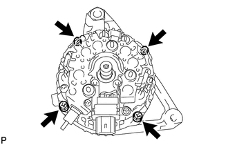
5. REMOVE GENERATOR COIL ASSEMBLY
|
(a) Remove the 4 bolts. |
|
|
(b) Using SST, remove the generator coil. SST: 09950-40011 09951-04020 09952-04010 09953-04020 09954-04010 09955-04071 09957-04010 |
|
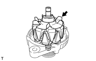
6. REMOVE GENERATOR ROTOR ASSEMBLY
|
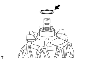
(a) Remove the generator washer. |
|
|
(b) Remove the generator rotor assembly. |
|
 Removal
REMOVAL
PROCEDURE
1. DISCONNECT CABLE FROM NEGATIVE BATTERY TERMINAL
NOTICE:
When disconnecting the cable, some systems need to be initialized after the cable
is reconnected (See page ).
2. RE ...
 Inspection
INSPECTION
PROCEDURE
1. INSPECT GENERATOR PULLEY WITH CLUTCH
(a) Hold the center of the pulley, and confirm that the outer ring turns
counterclockwise and does not turn clockwise.
...
Other materials about Toyota Venza:
Noise Occurs from Generator while Engine is Running
PROCEDURE
1.
CHECK LOOSENESS OF V-RIBBED BELT
(a) Check the tension of the belt by pushing it down with a finger.
OK:
The tension of the belt is enough.
NG
REPLACE V-RIBBED BELT TENSIONER ASSEMBLY
...
Disassembly
DISASSEMBLY
PROCEDURE
1. REMOVE FRONT TRANSAXLE CASE OIL SEAL
(a) Using SST, remove the front transaxle case oil seal from the transaxle
housing.
SST: 09308-00010
2. REMOVE TRANSAXLE CASE OIL ...
Sliding Roof Switch Assembly
Components
COMPONENTS
ILLUSTRATION
Removal
REMOVAL
PROCEDURE
1. REMOVE MAP LIGHT ASSEMBLY
Inspection
INSPECTION
PROCEDURE
1. INSPECT SLIDING ROOF SWITCH (ROOF CONSOLE BOX ASSEMBLY)
(a) Measure the resistance according to the value(s) in ...

0.1305