Toyota Venza: AVC-LAN Circuit
DESCRIPTION
Each unit of the navigation system connected to the AVC-LAN (communication bus) transmits switch signals via AVC-LAN communication.
If a short to +B or short to ground occurs in the AVC-LAN, the navigation system will not function normally because communication is not possible.
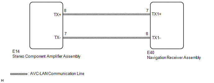
WIRING DIAGRAM
CAUTION / NOTICE / HINT
HINT:
The navigation receiver assembly is the master unit.
PROCEDURE
|
1. |
INSPECT NAVIGATION RECEIVER ASSEMBLY |
|
(a) Remove the navigation receiver assembly (See page
|
|
.gif) ).
).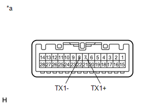
(b) Measure the resistance according to the value(s) in the table below.
Standard Resistance:
|
Tester Connection |
Condition |
Specified Condition |
|---|---|---|
|
7 (TX1+) - 8 (TX1-) |
Always |
60 to 80 Ω |
|
*a |
Component without harness connected (Navigation Receiver Assembly) |
| NG | .gif) |
REPLACE NAVIGATION RECEIVER ASSEMBLY |
|
.gif)
|
2. |
CHECK HARNESS AND CONNECTOR (AVC-LAN CIRCUIT) |
(a) Disconnect the E40 navigation receiver assembly connector.
(b) Disconnect the E14 stereo component amplifier assembly connector.
(c) Measure the resistance according to the value(s) in the table below.
Standard Resistance:
|
Tester Connection |
Condition |
Specified Condition |
|---|---|---|
|
E14-8 (TX+) - E40-7 (TX1+) |
Always |
Below 1 Ω |
|
E14-7 (TX-) - E40-8 (TX1-) |
Always |
Below 1 Ω |
|
E14-8 (TX+) - Body ground |
Always |
10 kΩ or higher |
|
E14-7 (TX-) - Body ground |
Always |
10 kΩ or higher |
| NG | |
REPAIR OR REPLACE HARNESS OR CONNECTOR |
|
|
3. |
INSPECT MALFUNCTIONING PARTS |
(a) Disconnect and reconnect each slave unit one by one until the master unit returns to normal.
HINT:
- Check all slave units.
- If disconnecting a slave unit causes the master unit to return to normal, the slave unit is defective and should be replaced.
OK:
Master unit returns to normal.
| OK | |
REPLACE MALFUNCTIONING PARTS |
| NG | |
REPLACE NAVIGATION RECEIVER ASSEMBLY |
 Mute Signal Circuit between Navigation Receiver Assembly and Stereo Component
Amplifier
Mute Signal Circuit between Navigation Receiver Assembly and Stereo Component
Amplifier
DESCRIPTION
This circuit sends a signal to the stereo component amplifier assembly to mute
noise. Due to this, the noise produced by changing the sound source ceases.
If there is an open in the ci ...
 Navigation Voice Circuit
DESCRIPTION
This circuit is used when the voice switch of the steering pad switch assembly
is pushed.
Using this circuit, the navigation receiver assembly sends signals to the stereo
component a ...
Other materials about Toyota Venza:
Power Back Door Closer Switch
Components
COMPONENTS
ILLUSTRATION
Removal
REMOVAL
PROCEDURE
1. REMOVE BACK DOOR PANEL TRIM ASSEMBLY
2. REMOVE POWER BACK DOOR CLOSER SWITCH ASSEMBLY
(a) Disconnect the connector.
(b) ...
Removal
REMOVAL
CAUTION / NOTICE / HINT
HINT:
Use the same procedure for the RH side and LH side.
The following procedure is for the LH side.
The rear speed sensor is a component of the rear axle hub and bearing
assembly. If the sensor malfuncti ...
Crankshaft Position Sensor "A" Circuit (P0335,P0339)
DESCRIPTION
The crankshaft position sensor system consists of a crank angle sensor plate
and a pickup coil.
The sensor plate has 34 teeth and is installed on the crankshaft. The pickup
coil is made of wound copper wire, an iron core and magnet. The senso ...

0.1556