Toyota Venza: Hydraulic Test
HYDRAULIC TEST
1. PERFORM HYDRAULIC TEST
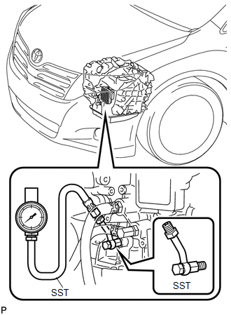
(a) Measure the line pressure.
CAUTION:
The line pressure test should always be carried out with at least 2 people. One person should observe the condition of wheels and wheel chocks while the other is performing the test.
NOTICE:
- Perform a test at the normal operating Automatic Transmission Fluid (ATF) temperature: 50 to 80°C (122 to 176°F)
- Be careful to prevent the SST hose from interfering with the exhaust pipe.
- This check must be conducted after checking and confirming that the engine is normal.
- Perform the test with the A/C off.
- Do not perform the stall test for longer than 5 seconds.
- When performing the stall speed test repeatedly, wait for 15 seconds or more between tests.
(1) Warm up the Automatic Transmission Fluid (ATF).
(2) Lift the vehicle up.
(3) Remove the engine under cover.
(4) Remove the test plug on the transaxle case front left side and install the SST.
SST: 09992-00095
09992-00231
09992-00271
(5) Lower the vehicle.
(6) Fully apply the parking brake and chock the 4 wheels.
(7) Connect the Techstream to the DLC3.
(8) Start the engine.
(9) Enter the following menus: Powertrain / ECT / Active Test / Control the Shift Position.
(10) Move the shift lever to D, and then use the Techstream to hold 3rd gear using Active Test. Measure the line pressure while the engine is idling.
Specified Line Pressure|
Condition |
D Position kPa (kgf/cm2, psi) |
|---|---|
|
Idling |
360 to 430 kPa (3.7 to 4.4 kgf/cm2, 52 to 62 psi) |
(11) Turn the ignition switch off.
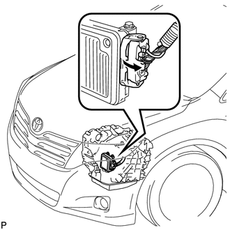
(12) Disconnect the connector of the TCM.
HINT:
Disconnect the connector only when performing the D position stall test.
(13) Start the engine.
(14) Firmly depress the brake pedal, move the shift lever to D, depress the accelerator pedal all the way down, and check the line pressure while the stall test is performed.
Specified Line Pressure|
Condition |
D Position kPa (kgf/cm2, psi) |
|---|---|
|
Stall test |
1160 to 1350 kPa (11.8 to 13.8 kgf/cm2, 168 to 196 psi) |
(15) Turn the ignition switch off.
(16) Connect the TCM connector, depress the brake pedal firmly, move the shift lever to R, and check that the line pressure while the engine is idling and during the stall test.
Specified Line Pressure|
Condition |
R Position kPa (kgf/cm2, psi) |
|---|---|
|
Idling |
800 to 950 kPa (8.2 to 9.7 kgf/cm2, 116 to 138 psi) |
|
Stall test |
1900 to 2200 kPa (19.4 to 22.4 kgf/cm2, 276 to 319 psi) |
(17) Remove the SST, install the test plug.
(18) Clear the DTCs.
Evaluation|
Test Result |
Possible Cause |
|---|---|
|
Measured values are higher than the specified value in all positions |
|
|
Measured values are lower than the specified value in all positions |
|
|
Pressure is low in D only |
|
|
Pressure is low in R only |
|
 Road Test
ROAD TEST
1. PROBLEM SYMPTOM CONFIRMATION
(a) Based on the result of the customer problem analysis, try to reproduce the
symptoms. If the problem is that the transaxle does not shift up, shift dow ...
 Manual Shifting Test
MANUAL SHIFTING TEST
1. PERFORM MANUAL SHIFTING TEST
HINT:
Using this test, it can be determined whether a problem is in an electrical
circuit or if it is a mechanical problem in the tr ...
Other materials about Toyota Venza:
Removal
REMOVAL
PROCEDURE
1. PRECAUTION
NOTICE:
Be sure to read Precaution thoroughly before servicing (See page
).
2. REMOVE SHIFT LEVER ASSEMBLY
(See page )
3. DISCONNECT INSTRUMENT PANEL WIRE ASSEMBLY
(a) Check that the ignition switch is off.
(b) Check ...
On-vehicle Inspection
ON-VEHICLE INSPECTION
PROCEDURE
1. INSPECT DRIVER SIDE SEAT BELT WARNING
(a) Turn the ignition switch to ON.
(b) When the driver side seat belt is not fastened, check that the driver side
seat belt warning light on the combination meter assembly blinks.
...
Inspection
INSPECTION
PROCEDURE
1. INSPECT COURTESY LIGHT SWITCH
(a) Measure the resistance according to the value(s) in the table below.
Standard Resistance:
Tester Connection
Switch Condition
Specified Condition
...

0.163