Toyota Venza: Components
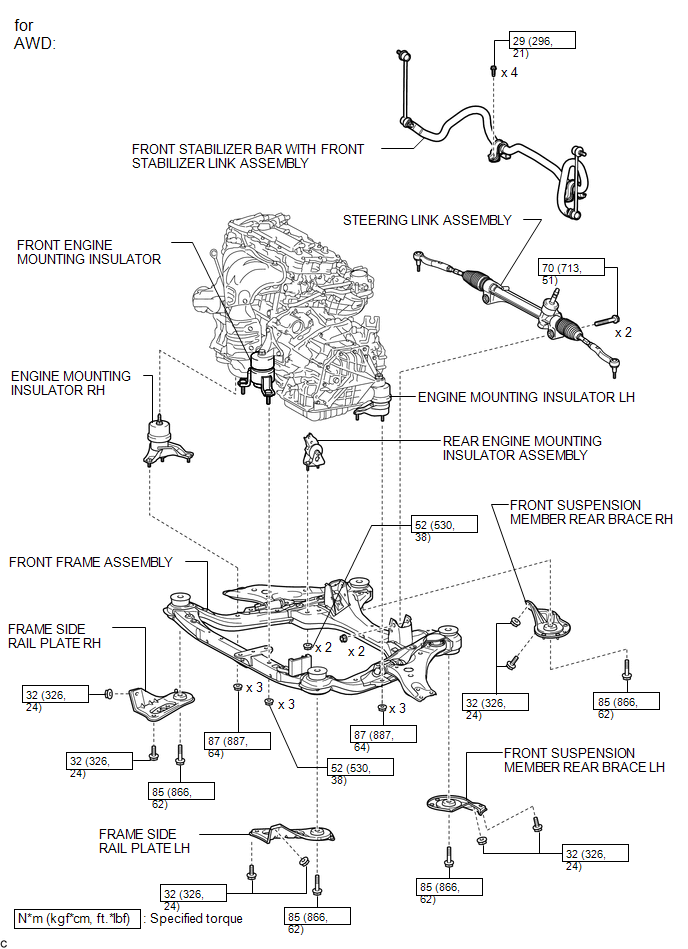
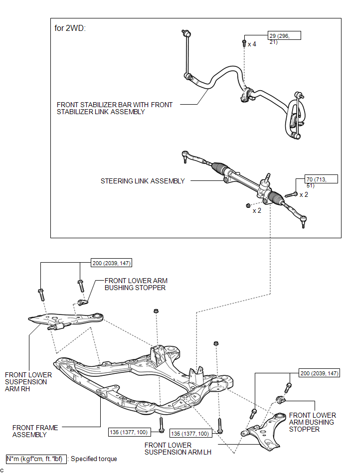
COMPONENTS
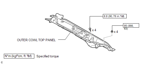
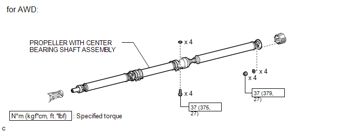
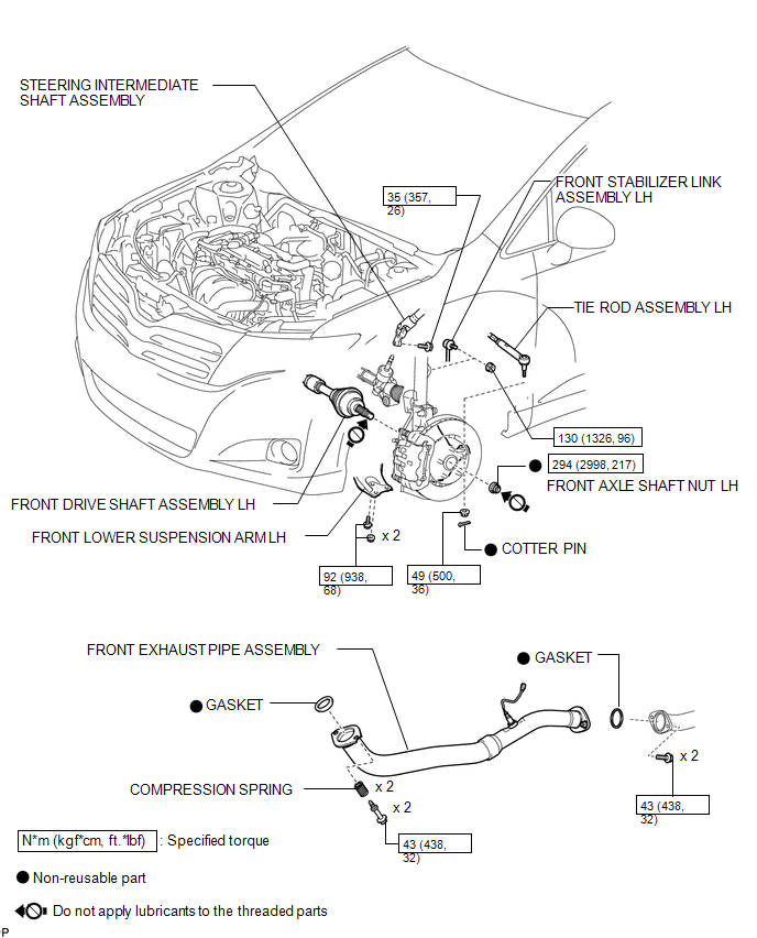
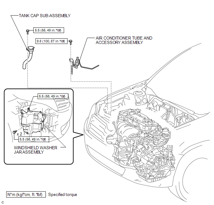
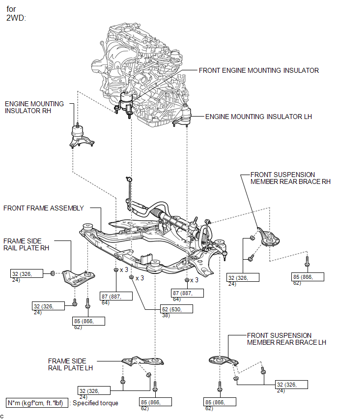
ILLUSTRATION
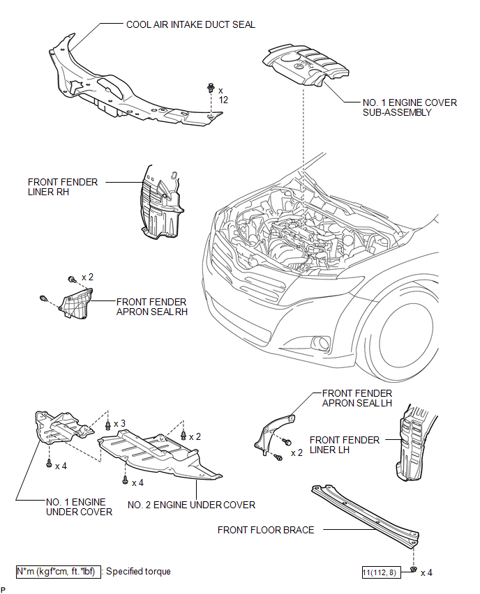
ILLUSTRATION
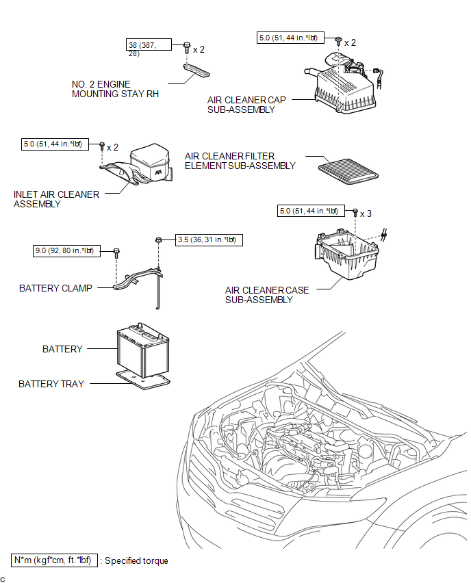
ILLUSTRATION
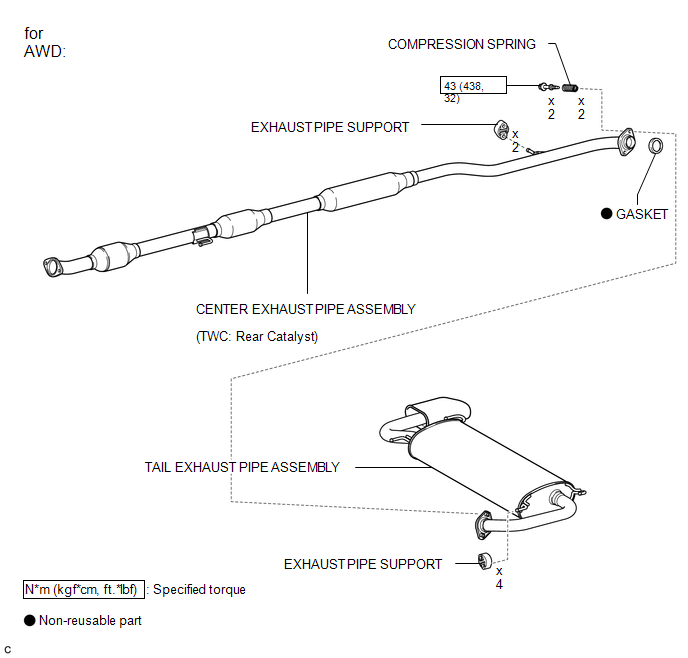
ILLUSTRATION
ILLUSTRATION
ILLUSTRATION
ILLUSTRATION
ILLUSTRATION
ILLUSTRATION
ILLUSTRATION
ILLUSTRATION
.png)

 Removal
REMOVAL
PROCEDURE
1. ALIGN FRONT WHEELS FACING STRAIGHT AHEAD
2. DISCONNECT CABLE FROM NEGATIVE BATTERY TERMINAL
NOTICE:
When disconnecting the cable, some systems need to be initialized after th ...
Other materials about Toyota Venza:
Installation
INSTALLATION
PROCEDURE
1. INSTALL INSTRUMENT PANEL WIRE ASSEMBLY
(a) Connect the vent hole connector of the instrument panel wire to the
front passenger airbag assembly.
Text in Illustration
*1
Vent Hol ...
Alarm
The system sounds the alarm and flashes lights when forcible entry is detected.
- Triggering of the alarm
The alarm is triggered in the following situations when the alarm is set.
• A locked door is unlocked or opened in any way other than by using ...
Precaution
PRECAUTION
NOTICE:
When disconnecting the cable from the negative (-) battery terminal, initialize
the following systems after the cable is reconnected.
System Name
See Procedure
Back Door Closer System
...

0.1376