Toyota Venza: Removal
REMOVAL
PROCEDURE
1. DISCONNECT CABLE FROM NEGATIVE BATTERY TERMINAL
NOTICE:
When disconnecting the cable, some systems need to be initialized after the cable
is reconnected (See page .gif) ).
).
2. REMOVE RADIATOR RESERVE TANK ASSEMBLY
|
(a) Remove the radiator reserve tank assembly. |
|
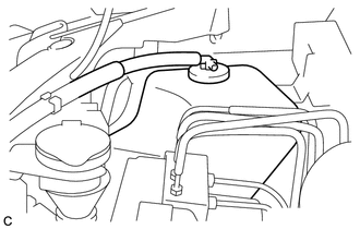
(b) Remove the radiator reserve tank cap assembly.
3. REMOVE BRAKE ACTUATOR WITH BRACKET
|
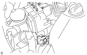
(a) Remove the clamp and separate the suction hose sub-assembly from the brake actuator bracket assembly. |
|
|
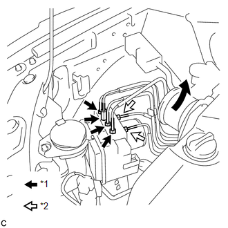
(b) Using union nut wrenches (10 mm and 12 mm), disconnect the 6 brake lines from the brake actuator with bracket. Text in Illustration
|
|
|
(c) Use tags or make a memo to identify the places to reconnect. Text in Illustration
|
|
|
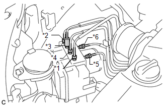
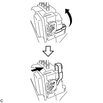
(d) Release the lock lever and disconnect the brake actuator connector. NOTICE: Be careful not to allow brake fluid to enter the removed connector. |
|
|
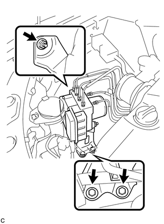
(e) Remove the nut, 2 bolts and brake actuator with bracket from the body. NOTICE: Do not damage the brake lines or wire harness. |
|
4. REMOVE BRAKE ACTUATOR ASSEMBLY
|
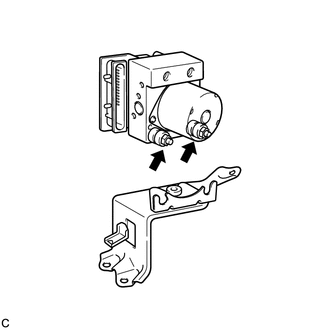
(a) Loosen the 2 nuts and remove the brake actuator assembly from the brake actuator bracket assembly. |
|
 On-vehicle Inspection
ON-VEHICLE INSPECTION
PROCEDURE
1. CONNECT TECHSTREAM
(a) Connect the Techstream to the DLC3.
(b) Start the engine and run it at idle.
(c) Enter the following menus: Chassis / ABS/VSC/TRAC / Acti ...
 Installation
INSTALLATION
PROCEDURE
1. INSTALL BRAKE ACTUATOR ASSEMBLY
(a) Install the brake actuator assembly to the brake actuator bracket
assembly with the 2 nuts.
Torque:
8.0 N·m {82 ...
Other materials about Toyota Venza:
Random / Multiple Cylinder Misfire Detected (P0300-P0304)
DESCRIPTION
When the engine misfires, high concentrations of hydrocarbons (HC) enter the
exhaust gas. Extremely high hydrocarbon concentration levels can cause an increase
in exhaust emission levels. Extremely high concentrations of hydrocarbons can also ...
Customize Parameters
CUSTOMIZE PARAMETERS
1. CUSTOMIZING FUNCTION WITH TECHSTREAM
HINT:
The following items can be customized.
NOTICE:
When the customer requests a change in a function, first make sure that
the function can be customized.
Be sure to make a not ...
Front Passenger Side Seat Belt Warning Light Malfunction
DESCRIPTION
The occupant classification ECU detects the state of the front seat inner belt
assembly RH and load sensor when the front passenger side seat is occupied with
the ignition switch ON. If the front passenger side seat belt is not fastened, the
...

0.1177