Toyota Venza: Headlight Leveling ECU Power Source Circuit
DESCRIPTION
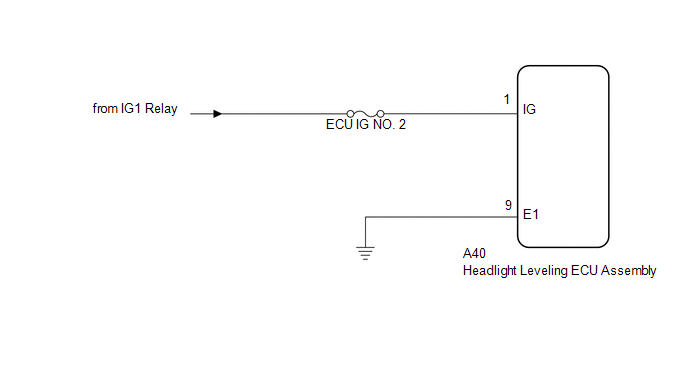
This circuit detects the state of the ignition switch, and sends it to the headlight leveling ECU assembly.
WIRING DIAGRAM
CAUTION / NOTICE / HINT
NOTICE:
Inspect the fuses for circuits related to this system before performing the following inspection procedure.
PROCEDURE
|
1. |
CHECK HARNESS AND CONNECTOR (BATTERY - HEADLIGHT LEVELING ECU ASSEMBLY) |
|
(a) Disconnect the A40 headlight leveling ECU assembly connector. |
|
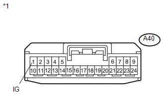
(b) Measure the voltage according to the value(s) in the table below.
Standard Voltage:
|
Tester Connection |
Switch Condition |
Specified Condition |
|---|---|---|
|
A40-1 (IG) - Body ground |
Ignition switch ON |
11 to 14 V |
|
A40-1 (IG) - Body ground |
Ignition switch off |
Below 1 V |
|
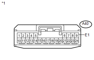
*1 |
Front view of wire harness connector (to Headlight Leveling ECU assembly) |
| NG | .gif) |
REPAIR OR REPLACE HARNESS OR CONNECTOR |
|
.gif)
|
2. |
CHECK HARNESS AND CONNECTOR (HEADLIGHT LEVELING ECU ASSEMBLY - BODY GROUND) |
|
(a) Measure the resistance according to the value(s) in the table below. Standard Resistance:
|
|
| OK | |
PROCEED TO NEXT SUSPECTED AREA SHOWN IN PROBLEM SYMPTOMS TABLE |
| NG | |
REPAIR OR REPLACE HARNESS OR CONNECTOR |
 Headlight Beam Level Control Actuator Circuit
DESCRIPTION
The headlight leveling ECU assembly actuates the headlight leveling motor according
to vehicle conditions.
WIRING DIAGRAM
PROCEDURE
1.
READ VALUE USING TECHS ...
 Indicator Circuit
DESCRIPTION
The headlight beam level control system indicator light in the combination meter
assembly comes on for approximately 3 seconds when the ignition switch is turned
to ON. The indicator ...
Other materials about Toyota Venza:
On-vehicle Inspection
ON-VEHICLE INSPECTION
PROCEDURE
1. INSPECT FOR COOLANT LEAK
HINT:
The sliding surface inside the engine water pump assembly is lubricated
by engine coolant. As some engine coolant is discharged during normal operation,
engine coolant residu ...
Inspection
INSPECTION
PROCEDURE
1. INSPECT FRONT DRIVE SHAFT ASSEMBLY
(a) Check whether the drive shaft dimensions are within the following
specifications.
Text in Illustration
*A
LH
*B
...
Disassembly
DISASSEMBLY
PROCEDURE
1. REMOVE UPPER BACK WINDOW PANEL TRIM
(a) Disengage the 4 clips and 4 claws, and remove the upper back window
panel trim.
2. REMOVE BACK DOOR PANEL TRIM ASSEMBLY
...

0.1289