Toyota Venza: Headlight Beam Level Control Actuator Circuit
DESCRIPTION
The headlight leveling ECU assembly actuates the headlight leveling motor according to vehicle conditions.
WIRING DIAGRAM

PROCEDURE
|
1. |
READ VALUE USING TECHSTREAM |
(a) Connect the Techstream to the DLC3.
(b) Turn the ignition switch to ON.
(c) Turn the Techstream on.
(d) Enter the following menus: Body Electrical / HL Auto Leveling / Active Test.
(e) Check that the motors operate.
HL Auto Leveling|
Tester Display |
Test Part |
Control Range |
Diagnostic Note |
|---|---|---|---|
|
Drive The Leveling Motor |
Leveling motor |
UP/OFF |
- |
|
DOWN/OFF |
- |
OK:
Headlight leveling motors operate normally.
| OK | .gif) |
PROCEED TO NEXT SUSPECTED AREA SHOWN IN PROBLEM SYMPTOMS TABLE |
|
.gif)
|
2. |
CHECK HARNESS AND CONNECTOR (HEADLIGHT LEVELING MOTOR - HEADLIGHT LEVELING ECU ASSEMBLY) |
(a) Disconnect the A40 headlight leveling ECU connector.
(b) Disconnect the A17 or A16 headlight leveling motor connector.
(c) Measure the resistance according to the value(s) in the table below.
Standard Resistance:
LH Side|
Tester Connection |
Condition |
Specified Condition |
|---|---|---|
|
A40-18 (LHT) - A17-2 (LH T) |
Always |
Below 1 Ω |
|
A40-11 (LH+) - A17-3 (LHM+) |
Always |
Below 1 Ω |
|
A40-24 (LH-) - A17-1 (LHM-) |
Always |
Below 1 Ω |
|
A40-18 (LHT) - Body ground |
Always |
10 kΩ or higher |
|
A40-11 (LH+) - Body ground |
Always |
10 kΩ or higher |
|
A40-24 (LH-) - Body ground |
Always |
10 kΩ or higher |
|
Tester Connection |
Condition |
Specified Condition |
|---|---|---|
|
A40-17 (RHT) - A16-2 (RH T) |
Always |
Below 1 Ω |
|
A40-10 (RH+) - A16-3 (RHM+) |
Always |
Below 1 Ω |
|
A40-23 (RH-) - A16-1 (RHM-) |
Always |
Below 1 Ω |
|
A40-17 (RHT) - Body ground |
Always |
10 kΩ or higher |
|
A40-10 (RH+) - Body ground |
Always |
10 kΩ or higher |
|
A40-23 (RH-) - Body ground |
Always |
10 kΩ or higher |
|
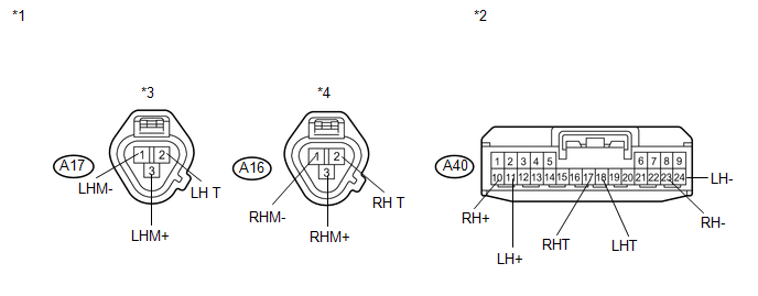
*1 |
Front view of wire harness connector (to Headlight Leveling Motor (Headlight Unit)) |
*3 |
LH Side |
|
*2 |
Front view of wire harness connector (to Headlight Leveling ECU Assembly) |
*4 |
RH Side |
| NG | |
REPAIR OR REPLACE HARNESS OR CONNECTOR |
|
|
3. |
REPLACE HEADLIGHT LEVELING MOTOR (HEADLIGHT UNIT) |
(a) Temporarily replace the headlight leveling motor with a new or normally functioning
one (See page .gif) ).
).
(b) Perform the Active Test of the leveling motors.
OK:
Headlight leveling motors operate normally.
| OK | |
PROCEED TO NEXT SUSPECTED AREA SHOWN IN PROBLEM SYMPTOMS TABLE |
| NG | |
REPLACE HEADLIGHT LEVELING ECU ASSEMBLY |
 Taillight Relay Circuit
DESCRIPTION
The main body ECU (driver side junction block assembly) controls the operation
of the TAIL relay.
WIRING DIAGRAM
CAUTION / NOTICE / HINT
NOTICE:
Inspect the fuses for circuits rel ...
 Headlight Leveling ECU Power Source Circuit
DESCRIPTION
This circuit detects the state of the ignition switch, and sends it to the headlight
leveling ECU assembly.
WIRING DIAGRAM
CAUTION / NOTICE / HINT
NOTICE:
Inspect the fuses for ci ...
Other materials about Toyota Venza:
Diagnostic Trouble Code Chart
DIAGNOSTIC TROUBLE CODE CHART
Meter / Gauge System
DTC Code
Detection Item
Trouble Area
See page
B1500
Fuel Sender Open Detected
1. Harness or connector
2. Combination mete ...
How To Proceed With Troubleshooting
CAUTION / NOTICE / HINT
HINT:
Use the following procedure to troubleshoot.
PROCEDURE
1.
VEHICLE BROUGHT TO WORKSHOP
NEXT
2.
CUSTOMER PR ...
Installation
INSTALLATION
CAUTION / NOTICE / HINT
NOTICE:
When disconnecting the steering intermediate shaft assembly and pinion shaft
of the steering gear assembly, be sure to place matchmarks before servicing.
PROCEDURE
1. INSTALL TIE ROD ASSEMBLY LH
( ...

0.1309