Toyota Venza: Indicator Circuit
DESCRIPTION
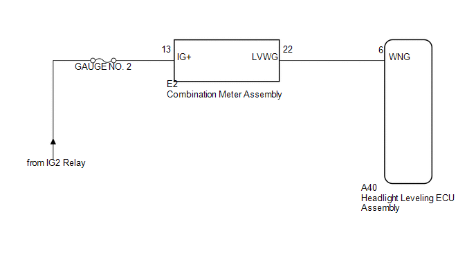
The headlight beam level control system indicator light in the combination meter assembly comes on for approximately 3 seconds when the ignition switch is turned to ON. The indicator light also comes on when the headlight leveling ECU assembly detects a malfunction.
WIRING DIAGRAM
PROCEDURE
|
1. |
CHECK HARNESS AND CONNECTOR (BATTERY - COMBINATION METER ASSEMBLY) |
|
(a) Disconnect the E2 combination meter assembly connector. |
|
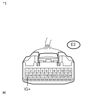
(b) Measure the voltage according to the value(s) in the table below.
Standard Voltage:
|
Tester Connection |
Switch Condition |
Specified Condition |
|---|---|---|
|
E2-13 (IG+) - Body ground |
Ignition switch ON |
11 to 14 V |
|
Ignition switch off |
Below 1 V |
|
*1 |
Front view of wire harness connector (to Combination Meter Assembly) |
| NG | .gif) |
REPAIR OR REPLACE HARNESS OR CONNECTOR |
|
.gif)
|
2. |
CHECK HARNESS AND CONNECTOR (COMBINATION METER ASSEMBLY - HEADLIGHT LEVELING ECU ASSEMBLY) |
|
(a) Disconnect the A40 headlight leveling ECU assembly connector. |
|
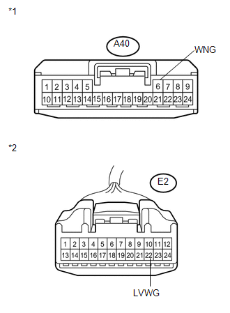
(b) Measure the resistance according to the value(s) in the table below.
Standard Resistance:
|
Tester Connection |
Condition |
Specified Condition |
|---|---|---|
|
A40-6 (WNG) - E2-22 (LVWG) |
Always |
Below 1 Ω |
|
A40-6 (WNG) - Body ground |
Always |
10 kΩ or higher |
|
*1 |
Front view of wire harness connector (to Headlight Leveling ECU Assembly) |
|
*2 |
Front view of wire harness connector (to Combination Meter Assembly) |
| NG | |
REPAIR OR REPLACE HARNESS OR CONNECTOR |
|
|
3. |
INSPECT COMBINATION METER ASSEMBLY |
|
(a) Reconnect the E2 combination meter assembly connector. |
|
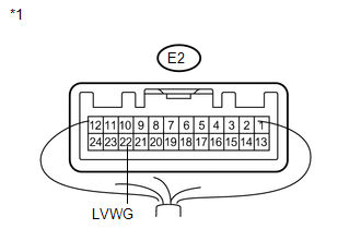
(b) Measure the voltage according to the value(s) in the table below.
Standard Voltage:
|
Tester Connection |
Switch Condition |
Specified Condition |
|---|---|---|
|
E2-22 (LVWG) - Body ground |
Ignition switch ON |
11 to 14 V |
|
*1 |
Component with harness connected (Combination Meter Assembly) |
| OK | |
PROCEED TO NEXT SUSPECTED AREA SHOWN IN PROBLEM SYMPTOMS TABLE |
| NG | |
REPLACE COMBINATION METER ASSEMBLY |
 Headlight Leveling ECU Power Source Circuit
DESCRIPTION
This circuit detects the state of the ignition switch, and sends it to the headlight
leveling ECU assembly.
WIRING DIAGRAM
CAUTION / NOTICE / HINT
NOTICE:
Inspect the fuses for ci ...
 Speed Signal Circuit
DESCRIPTION
The headlight leveling ECU assembly receives the vehicle speed signal from the
combination meter assembly.
HINT:
A voltage of 12 V or 5 V is output from each ECU and then inpu ...
Other materials about Toyota Venza:
Inspection
INSPECTION
PROCEDURE
1. INSPECT NO. 1 VALVE ROCKER ARM SUB-ASSEMBLY
(a) Turn the roller by hand to check that it turns smoothly.
If the roller does not turn smoothly, replace the No. 1 valve rocker
arm sub-assembly.
...
Variation Error (B2453)
DESCRIPTION
This DTC is stored if the headlight leveling ECU assembly for another destination
is installed on the vehicle.
DTC No.
DTC Detecting Condition
Trouble Area
B2453
The headlight levelin ...
Removal
REMOVAL
CAUTION / NOTICE / HINT
HINT:
Use the same procedure for the LH side and RH side.
The following procedure listed below is for the LH side.
PROCEDURE
1. REMOVE FRONT WHEEL
2. REMOVE FRONT WIPER ARM HEAD CAP
3. REMOVE FRONT WI ...

0.114