Toyota Venza: Installation
INSTALLATION
PROCEDURE
1. INSTALL CENTER AIRBAG SENSOR ASSEMBLY
(a) Check that the ignition switch is off.
(b) Check that the cable is disconnected from the negative (-) battery terminal.
CAUTION:
Wait at least 90 seconds after disconnecting the cable from the negative (-) battery terminal to disable the SRS system.
|
(c) Install the center airbag sensor assembly with the 3 bolts. Text in Illustration
Torque: 18 N·m {178 kgf·cm, 13 ft·lbf} NOTICE:
|
|
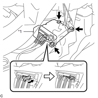
(d) Connect the connector to the center airbag sensor assembly as shown in the illustration.
NOTICE:
When connecting the airbag connector, take care not to damage the airbag wire harness.
(e) Check that the waterproof sheet is properly set.
(f) Check that there is no looseness in the installation parts of the center airbag sensor assembly.
2. INSTALL CONSOLE BOX SUB-ASSEMBLY
.gif)
3. INSTALL SHIFT LEVER KNOB SUB-ASSEMBLY
4. INSTALL CONSOLE BOX ASSEMBLY
5. INSTALL NO. 2 CONSOLE BOX CARPET
6. INSTALL LOWER INSTRUMENT PANEL SUB-ASSEMBLY
7. INSTALL NO. 2 INSTRUMENT PANEL UNDER COVER SUB-ASSEMBLY
8. INSTALL COWL SIDE TRIM SUB-ASSEMBLY RH
9. INSTALL FRONT DOOR SCUFF PLATE RH
10. INSTALL AIR CONDITIONER CONTROL ASSEMBLY
11. INSTALL UPPER CONSOLE PANEL SUB-ASSEMBLY (w/o Seat Heater System)
12. INSTALL UPPER CONSOLE PANEL SUB-ASSEMBLY (w/ Seat Heater System)
13. INSTALL LOWER NO. 1 INSTRUMENT PANEL FINISH PANEL
14. INSTALL COWL SIDE TRIM SUB-ASSEMBLY LH
15. INSTALL FRONT DOOR SCUFF PLATE LH
16. CONNECT CABLE TO NEGATIVE BATTERY TERMINAL
NOTICE:
When disconnecting the cable, some systems need to be initialized after the cable
is reconnected (See page ).
17. PERFORM DIAGNOSTIC SYSTEM CHECK
(a) Perform a diagnostic system check (See page
).
18. INSPECT SRS WARNING LIGHT
(a) Inspect the SRS warning light (See page
).
 Removal
REMOVAL
PROCEDURE
1. PRECAUTION
CAUTION:
Be sure to read Precaution thoroughly before servicing (See page
).
2. DISCONNECT CABLE FROM NEGATIVE BATTERY TERMINAL
CAUTION:
Wait at least 90 secon ...

Other materials about Toyota Venza:
How To Proceed With Troubleshooting
CAUTION / NOTICE / HINT
HINT:
Use the following procedure to troubleshoot the air conditioning system.
*: Use the Techstream.
PROCEDURE
1.
VEHICLE BROUGHT TO WORKSHOP
NEXT
...
Rear Spoiler
Components
COMPONENTS
ILLUSTRATION
Removal
REMOVAL
PROCEDURE
1. REMOVE UPPER BACK WINDOW PANEL TRIM
2. REMOVE REAR SPOILER ASSEMBLY
(a) Disconnect the connector.
(b) Remove the 2 hole ...
Lost Communication with Gateway Module (Power Management1) (U1002)
DESCRIPTION
The power management control ECU will store this DTC when no signals
can be received from the ECUs that have been memorized as those that are
connected to the CAN No. 2 bus.
When the power management control ECU receives a respo ...

0.1592