Toyota Venza: Installation
INSTALLATION
PROCEDURE
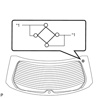
1. INSTALL NO. 2 BACK WINDOW GLASS SPACER
(a) Apply Primer G to the installation part of the No. 2 back window glass spacer.
HINT:
If primer is applied to an area that is not specified, wipe off the primer with a non-residue solvent before it dries.
|
(b) Install a new No. 2 back window glass spacer onto the back door glass, as shown in the illustration. Text in Illustration
NOTICE:
|
|
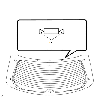
2. INSTALL NO. 1 BACK WINDOW GLASS SPACER
HINT:
Use the same procedure for the RH side and LH side.
3. INSTALL BACK DOOR GLASS SPACER
(a) Apply Primer G to the installation part of the back window glass spacer.
HINT:
If primer is applied to an area that is not specified, wipe off the primer with a non-residue solvent before it dries.
|
(b) Install 4 new back door glass spacers onto the back door glass, as shown in the illustration. Text in Illustration
NOTICE:
|
|
4. INSTALL BACK DOOR GLASS
(a) Using a brush, coat the installation surface on the vehicle body with Primer M.
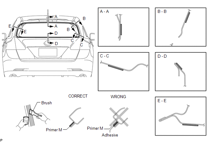
NOTICE:
- Do not coat the adhesive with Primer M.
- Do not apply too much primer.
- Allow the primer to dry for 3 minutes or more.
- Throw away any leftover primer.
HINT:
If an area other than that specified is coated by accident, wipe off the primer with a clean piece of cloth before it dries.
(b) Using a brush or a sponge, coat the application area of the adhesive with Primer G.
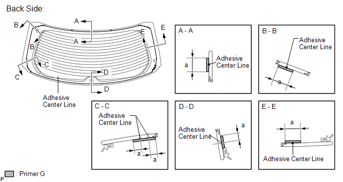
Standard Dimension:
|
Item |
Dimension |
|---|---|
|
a |
14.0 mm (0.551 in.) |
NOTICE:
- Do not apply too much primer.
- Allow the primer to dry for 3 minutes or more.
- Throw away any leftover primer.
HINT:
- Apply Primer G onto the ceramic notches.
- If an area other than that specified is coated by accident, wipe off the primer with a clean piece of cloth before it dries.
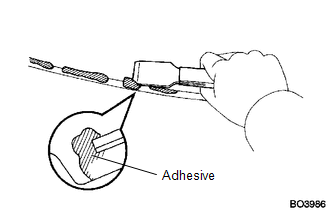
(c) Apply adhesive to the back door glass.
Adhesive:
Toyota Genuine Windshield Glass Adhesive or equivalent
|
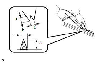
(1) Cut off the tip of the cartridge nozzle as shown in the illustration. Standard Dimension:
HINT: After cutting off the tip, use all the adhesive within the time described in the table below. Usage Time Frame:
|
|
(2) Load the sealer gun with cartridge.
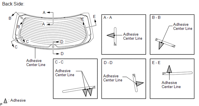
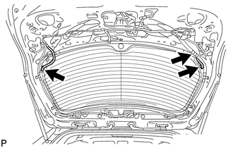
(3) Apply adhesive to the back door glass as shown in the illustration.
(d) Install the back door glass.
|
(1) Position the back door glass so that the matchmarks are aligned, and press it in gently along the rim (when glass without a clip is used). Text in Illustration
|
|
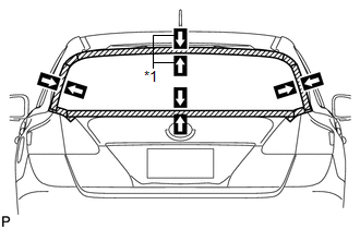
(2) Lightly press the back door glass to ensure that the back door glass is securely fit to the vehicle body (when glass without a clip is used).
HINT:
Press the glass with a force of 98 N (10 kgf, 22 lbf) or more.
|
(3) Using suction cups, engage the 4 clips to install the back door glass (when glass with all clips is used). NOTICE:
|
|
(4) Lightly press the front surface of the back door glass to ensure that the back door glass is securely fit to the vehicle body.
HINT:
Press the back door glass with a force of 98 N (10 kgf, 22 lbf) or more.
|
(5) Using a scraper, remove any excess or protruding adhesive. HINT: Apply adhesive onto the glass rim. |
|
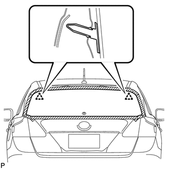
(6) Hold the back door glass using protective tape until applied adhesive becomes hard.
NOTICE:
Do not drive the vehicle within the time described in the table below.
Minimum Time:
|
Temperature |
Minimum Time prior to Driving Vehicle |
|---|---|
|
35°C (95°F) |
1 hour and 30 minutes |
|
20°C (68°F) |
5 hours |
|
5°C (41°F) |
24 hours |
|
(e) Connect the 3 connectors. |
|
5. INSPECT FOR LEAK AND REPAIR
(a) After the adhesive has hardened, apply water from the outside of the vehicle. Check that no water leaks into the cabin.
(b) If water leaks into the cabin, allow the water to dry and add adhesive.
(c) Remove the protective tape.
6. INSTALL REAR WIPER MOTOR AND BRACKET ASSEMBLY
.gif)
7. INSTALL REAR WIPER MOTOR GROMMET
8. INSTALL REAR WIPER ARM AND BLADE ASSEMBLY
9. INSTALL REAR WIPER ARM HEAD CAP
10. INSTALL REAR SPOILER ASSEMBLY
11. INSTALL BACK DOOR TRIM COVER RH
12. INSTALL BACK DOOR TRIM COVER LH (w/o Power Back Door)
13. INSTALL BACK DOOR TRIM COVER LH (w/ Power Back Door)
14. CONNECT POWER BACK DOOR ROD (w/ Power Back Door)
15. INSTALL BACK DOOR PANEL TRIM ASSEMBLY
16. INSTALL UPPER BACK WINDOW PANEL TRIM
 Components
COMPONENTS
ILLUSTRATION
ILLUSTRATION
ILLUSTRATION
...
 Removal
REMOVAL
PROCEDURE
1. REMOVE UPPER BACK WINDOW PANEL TRIM
2. REMOVE BACK DOOR PANEL TRIM ASSEMBLY
3. DISCONNECT POWER BACK DOOR ROD (w/ Power Back Door)
4. REMOVE BACK DOOR TRIM COVER LH ...
Other materials about Toyota Venza:
Switch Failure (B2342)
DESCRIPTION
This DTC is output when the sliding roof ECU (sliding roof drive gear sub-assembly)
detects that the sliding roof switch is stuck for 30 seconds or more.
DTC Code
DTC Detection Condition
Trouble Area
...
Installation
INSTALLATION
PROCEDURE
1. INSTALL REAR DRIVE SHAFT ASSEMBLY
(a) Align the shaft splines and install the rear drive shaft assembly
using a screwdriver and hammer.
NOTICE:
Set the snap ring with the opening facing downward.
...
Installation
INSTALLATION
PROCEDURE
1. INSTALL SEPARATE TYPE FRONT SEAT CUSHION COVER
(a) Using a tacker, install the separate type front seat cushion heater
to the end of the separate type front seat cushion cover with 25 new tack
pins.
NOTICE:
...

0.132