Toyota Venza: VC Output Circuit
DESCRIPTION
The ECM constantly generates 5 V of power from battery voltage supplied to the +B (BATT) terminal to operate the microprocessor. The ECM also provides this power to the sensors through the VC output circuit.
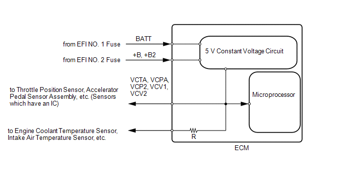
When the VC circuit is short-circuited, the microprocessor in the ECM and sensors that are supplied with power through the VC circuit are inactivated because the power is not supplied from the VC circuit. Under this condition, the system does not start up and the MIL does not illuminate even if the system malfunctions.
HINT:
Under normal conditions, the MIL is illuminated when the ignition switch is turned to ON. The MIL turns off when the engine is started.
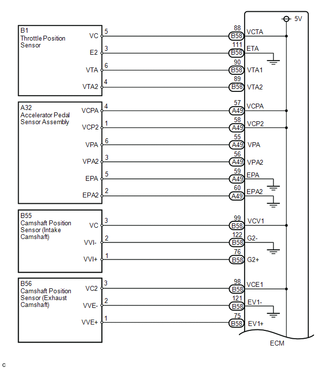
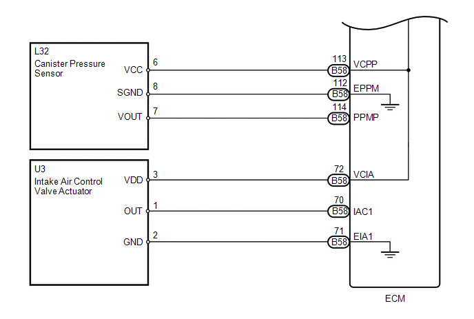
WIRING DIAGRAM
PROCEDURE
|
1. |
CHECK MIL |
(a) Check that the Malfunction Indicator Lamp (MIL) turns on when turning the ignition switch to ON.
OK:
MIL turns on.
| OK | .gif) |
PROCEED TO NEXT SUSPECTED AREA SHOWN IN PROBLEM SYMPTOMS TABLE |
|
.gif)
|
2. |
CHECK COMMUNICATION BETWEEN TECHSTREAM AND ECM |
(a) Connect the Techstream to the DLC3.
(b) Turn the ignition switch to ON.
(c) Turn the Techstream on.
(d) Check the communication between the Techstream and ECM.
|
Result |
Proceed to |
|---|---|
|
Communication is not possible |
A |
|
Communication is possible |
B |
| B | |
GO TO MIL CIRCUIT |
|
|
3. |
CHECK MIL (THROTTLE POSITION SENSOR) |
(a) Disconnect the throttle body connector.
(b) Turn the ignition switch to ON.
(c) Check the MIL.
|
Result |
Proceed to |
|---|---|
|
MIL does not illuminate |
A |
|
MIL illuminates |
B |
HINT:
Perform "Inspection After Repair" after replacing the throttle body (See page
.gif) ).
).
| B | |
REPLACE THROTTLE BODY |
|
|
4. |
CHECK MIL (ACCELERATOR PEDAL SENSOR ASSEMBLY) |
(a) Disconnect the accelerator pedal sensor assembly connector.
(b) Turn the ignition switch to ON.
(c) Check the MIL.
|
Result |
Proceed to |
|---|---|
|
MIL does not illuminate |
A |
|
MIL illuminates |
B |
| B | |
REPLACE ACCELERATOR PEDAL SENSOR ASSEMBLY |
|
|
5. |
CHECK MIL (CANISTER PUMP MODULE) |
(a) Disconnect the canister pump module connector.
(b) Turn the ignition switch to ON.
(c) Check the MIL.
|
Result |
Proceed to |
|---|---|
|
MIL does not illuminate |
A |
|
MIL illuminates |
B |
| B | |
REPLACE CHARCOAL CANISTER ASSEMBLY |
|
|
6. |
CHECK MIL (CAMSHAFT POSITION SENSOR (FOR INTAKE CAMSHAFT)) |
(a) Disconnect the camshaft position sensor (for intake camshaft) connector.
(b) Turn the ignition switch to ON.
(c) Check the MIL.
|
Result |
Proceed to |
|---|---|
|
MIL does not illuminate |
A |
|
MIL illuminates |
B |
| B | |
REPLACE CAMSHAFT POSITION SENSOR |
|
|
7. |
CHECK MIL (CAMSHAFT POSITION SENSOR (FOR EXHAUST CAMSHAFT)) |
(a) Disconnect the camshaft position sensor (for exhaust camshaft) connector.
(b) Turn the ignition switch to ON.
(c) Check the MIL.
|
Result |
Proceed to |
|---|---|
|
MIL does not illuminate |
A |
|
MIL illuminates |
B |
| B | |
REPLACE CAMSHAFT POSITION SENSOR |
|
|
8. |
CHECK MIL (INTAKE AIR CONTROL VALVE ACTUATOR) |
(a) Disconnect the intake air control valve actuator connector.
(b) Turn the ignition switch to ON.
(c) Check the MIL.
|
Result |
Proceed to |
|---|---|
|
MIL does not illuminate |
A |
|
MIL illuminates |
B |
| B | |
REPLACE INTAKE AIR CONTROL VALVE ACTUATOR |
|
|
9. |
CHECK HARNESS AND CONNECTOR (VC CIRCUIT) |
(a) Disconnect the throttle body connector.
(b) Disconnect the accelerator pedal sensor assembly connector.
(c) Disconnect the canister pump module connector.
(d) Disconnect the camshaft position sensor (for intake camshaft) connector.
(e) Disconnect the camshaft position sensor (for exhaust camshaft) connector.
(f) Disconnect the intake air control valve actuator connector.
(g) Disconnect the ECM connectors.
(h) Measure the resistance according to the value(s) in the table below.
Standard Resistance (Check for Short):
|
Tester Connection |
Condition |
Specified Condition |
|---|---|---|
|
A49-57 (VCPA) - Body ground |
Always |
10 kΩ or higher |
|
A49-58 (VCP2) - Body ground |
Always |
10 kΩ or higher |
|
B58-72 (VCIA) - Body ground |
Always |
10 kΩ or higher |
|
B58-88 (VCTA) - Body ground |
Always |
10 kΩ or higher |
|
B58-98 (VCE1) - Body ground |
Always |
10 kΩ or higher |
|
B58-99 (VCV1) - Body ground |
Always |
10 kΩ or higher |
|
B58-113 (VCPP) - Body ground |
Always |
10 kΩ or higher |
| OK | |
REPLACE ECM |
| NG | |
REPAIR OR REPLACE HARNESS OR CONNECTOR |
 ECM Power Source Circuit
DESCRIPTION
When the ignition switch is turned to ON, the battery voltage is applied to IGSW
of the ECM. The output signal from the MREL terminal of the ECM causes a current
to flow to the coil, ...
 Fuel Pump Control Circuit
DESCRIPTION
1. w/o Smart Key System
When the engine is cranked, the starter relay drive signal output from the ignition
switch is input into the STA terminal of the ECM, and the NE signal generate ...
Other materials about Toyota Venza:
Charge Warning Light Comes ON while Driving
PROCEDURE
1.
CHECK LOCK FUNCTION OF CLUTCH PULLEY
(a) Check the lock function with the pulley installed in the vehicle.
(1) Visually check that the rotor in the generator operates with the engine started.
(b) Check the lock ...
Front Sensor Communication Malfunction (C1AEC)
DESCRIPTION
This DTC is stored when there is an open or short circuit in the communication
line between the front sensors and the ECU, or when there is a malfunction in a
front sensor.
DTC No.
DTC Detection Condition
Trou ...
Engine Coolant Temperature Circuit Range / Performance Problem (P0116)
DESCRIPTION
Refer to DTC P0115 (See page ).
DTC No.
DTC Detection Condition
Trouble Area
P0116
When either of the following conditions is met (2 trip detection logic).
During engine ...

0.1414