Toyota Venza: Front Speed Sensor RH Circuit (C0200/31,C0205/32,C1271/71,C1272/72,C1330/35,C1331/36)
DESCRIPTION
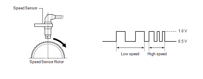
The speed sensor detects wheel speed and sends the appropriate signals to the skid control ECU. These signals are used for the ABS control system.
Speed sensor rotors have 48 serrations. The hall IC type speed sensor use the frequency of output pulses to detect the vehicle speed. Because the sensor outputs digital pulses, it can detect vehicle speeds even when the vehicle is nearly stationary.
DTCs C1271/71 and C1272/72 will be cleared when the speed sensor sends a vehicle speed signal or when Test Mode ends. DTCs C1271/71 and C1272/72 are output only in Test Mode.
|
DTC Code |
DTC Detection Condition |
Trouble Area |
|---|---|---|
|
C0200/31 C0205/32 |
Any of the following is detected:
|
|
|
C1330/35 C1331/36 |
An open or short in the speed sensor signal circuit. |
|
|
C1271/71 C1272/72 |
Detected only during Test Mode. |
|
HINT:
- DTCs C0200/31, C1271/71 and C1330/35 are for the front speed sensor RH.
- DTCs C0205/32, C1272/72 and C1331/36 are for the front speed sensor LH.
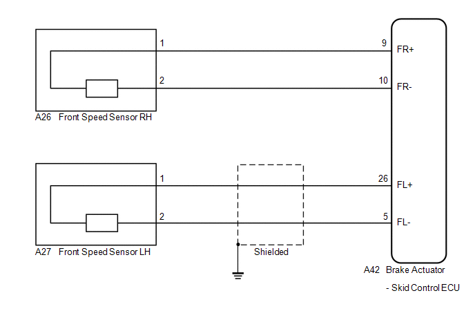
WIRING DIAGRAM
PROCEDURE
|
1. |
READ VALUE USING TECHSTREAM (FRONT SPEED SENSOR) |
(a) Connect the Techstream to the DLC3.
(b) Start the engine.
(c) Select the Data List on the Techstream (See page
.gif) ).
).
ABS/VSC/TRAC
|
Tester Display |
Measurement Item/Range |
Normal Condition |
Diagnostic Note |
|---|---|---|---|
|
FR Wheel Speed |
Front wheel speed sensor RH reading / Min.: 0 km/h (0 mph), Max.: 326 km/h (202 mph) |
Vehicle stopped: 0 km/h (0 mph) |
When driving at constant speed: No large fluctuations |
|
FL Wheel Speed |
Front wheel speed sensor LH reading / Min.: 0 km/h (0 mph), Max.: 326 km/h (202 mph) |
Vehicle stopped: 0 km/h (0 mph) |
When driving at constant speed: No large fluctuations |
(d) Check that the speed value output from the speed sensor displayed on the Techstream.
HINT:
Factors that affect the indicated vehicle speed include tire size, tire inflation,
and tire wear. The speed indicated on the speedometer has an allowable margin of
error. This can be tested using a speedometer tester (calibrated chassis dynamometer).
For details about testing and the margin of error, see the reference chart (See
page ).
OK:
The speed value output from the speed sensor displayed on the Techstream is the similar speed as indicated on the speedometer.
| NG | .gif) |
GO TO STEP 4 |
|
.gif)
|
2. |
PERFORM TEST MODE INSPECTION (SIGNAL CHECK) |
(a) Turn the ignition switch off.
(b) Perform sensor check in Test Mode Procedure (See page
).
OK:
All Test Mode DTCs are not output.
| NG | |
GO TO STEP 4 |
|
|
3. |
RECONFIRM DTC |
(a) Turn the ignition switch off.
(b) Clear the DTCs (See page ).
(c) Start the engine.
(d) Drive the vehicle at a speed of 45 km/h (28 mph) or more for at least 60 seconds.
(e) Check if the same DTC is recorded (See page
).
|
Result |
Proceed to |
|---|---|
|
DTCs (C0200/31, C0205/32, C1330/35 and C1331/36) are not output |
A |
|
DTCs (C0200/31, C0205/32, C1330/35 and/or C1331/36) are output |
B |
HINT:
If troubleshooting has been carried out according to Problem Symptoms Table,
refer back to the table and proceed to the next step (See page
).
| A | |
CHECK FOR INTERMITTENT PROBLEMS |
| B | |
GO TO STEP 8 |
|
4. |
CHECK FRONT SPEED SENSOR INSTALLATION |
|
(a) Turn the ignition switch off. |
|
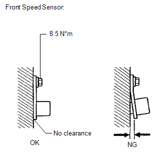
(b) Check the speed sensor installation.
OK:
There is no clearance between the sensor and the front steering knuckle.
The installation bolt is tightened properly.
Torque
8.5 N*m (87 kgf*cm, 75 in.*lbf)
| NG | |
INSTALL FRONT SPEED SENSOR CORRECTLY |
|
|
5. |
CHECK FRONT SPEED SENSOR TIP |
(a) Remove the front speed sensor (See page
).
(b) Check the speed sensor tip.
OK:
No scratches, oil, or foreign matter on the sensor tip.
NOTICE:
Check the speed sensor signal after cleaning or replacement (See page
).
| NG | |
CLEAN OR REPLACE FRONT SPEED SENSOR |
|
|
6. |
CHECK HARNESS AND CONNECTOR (SKID CONTROL ECU - FRONT SPEED SENSOR) |
|
(a) Install the front speed sensor. |
|
(b) Make sure that there is no looseness at the locking part and the connecting part of the connectors.
(c) Disconnect the skid control ECU connector and the front speed sensor connector.
(d) Measure the resistance according to the value(s) in the table below.
Standard Resistance:
for RH
|
Tester Connection |
Condition |
Specified Condition |
|---|---|---|
|
A42-9 (FR+) - A26-1 (FR+) |
Always |
Below 1 Ω |
|
A42-9 (FR+) - Body ground |
Always |
10 kΩ or higher |
|
A42-10 (FR-) - A26-2 (FR-) |
Always |
Below 1 Ω |
|
A42-10 (FR-) - Body ground |
Always |
10 kΩ or higher |
for LH
|
Tester Connection |
Condition |
Specified Condition |
|---|---|---|
|
A42-26 (FL+) - A27-1 (FL+) |
Always |
Below 1 Ω |
|
A42-26 (FL+) - Body ground |
Always |
10 kΩ or higher |
|
A42-5 (FL-) - A27-2 (FL-) |
Always |
Below 1 Ω |
|
A42-5 (FL-) - Body ground |
Always |
10 kΩ or higher |
|
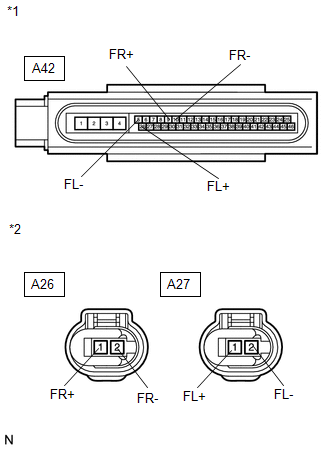
*1 |
Front view of wire harness connector (to Brake Actuator (Skid Control ECU)) |
|
*2 |
Front view of wire harness connector (to Front Speed Sensor) |
| NG | |
REPAIR OR REPLACE HARNESS OR CONNECTOR |
|
|
7. |
RECONFIRM DTC |
(a) Reconnect the skid control ECU connector and the front speed sensor connector.
(b) Clear the DTCs (See page ).
(c) Start the engine.
(d) Drive the vehicle at a speed of 45 km/h (28 mph) or more for at least 60 seconds.
(e) Check if the same DTC is recorded (See page
).
|
Result |
Proceed to |
|---|---|
|
DTCs (C0200/31, C0205/32, C1330/35 and/or C1331/36) are output |
A |
|
DTCs (C0200/31, C0205/32, C1330/35 and C1331/36) are not output |
B |
HINT:
If troubleshooting has been carried out according to Problem Symptoms Table,
refer back to the table and proceed to the next step (See page
).
| B | |
CHECK FOR INTERMITTENT PROBLEMS |
|
|
8. |
REPLACE FRONT SPEED SENSOR |
(a) Turn the ignition switch off.
(b) Replace the front speed sensor (See page
).
NOTICE:
Check the speed sensor signal after replacement (See page
).
|
|
9. |
RECONFIRM DTC |
(a) Clear the DTCs (See page ).
(b) Start the engine.
(c) Drive the vehicle at a speed of 45 km/h (28 mph) or more for at least 60 seconds.
(d) Check if the same DTC is recorded (See page
).
|
Result |
Proceed to |
|---|---|
|
DTCs (C0200/31, C0205/32, C1330/35 and/or C1331/36) are output |
A |
|
DTCs (C0200/31, C0205/32, C1330/35 and C1331/36) are not output |
B |
HINT:
If troubleshooting has been carried out according to Problem Symptoms Table,
refer back to the table and proceed to the next step (See page
).
| B | |
END |
|
|
10. |
REPLACE FRONT SPEED SENSOR ROTOR |
(a) Turn the ignition switch off.
(b) Remove the front drive shaft assembly (See page
).
(c) Replace the front drive outboard joint shaft assembly (front speed sensor
rotor) (See page ).
HINT:
If the front speed sensor rotor needs to be replaced, replace it together with the front drive outboard joint shaft assembly.
NOTICE:
Check the speed sensor signal after replacement (See page
).
|
|
11. |
RECONFIRM DTC |
(a) Install the front drive shaft assembly.
(b) Clear the DTCs (See page ).
(c) Start the engine.
(d) Drive the vehicle at a speed of 45 km/h (28 mph) or more for at least 60 seconds.
(e) Check if the same DTC is recorded (See page
).
|
Result |
Proceed to |
|---|---|
|
DTCs (C0200/31, C0205/32, C1330/35 and C1331/36) are not output |
A |
|
DTCs (C0200/31, C0205/32, C1330/35 and/or C1331/36) are output |
B |
HINT:
If troubleshooting has been carried out according to Problem Symptoms Table,
refer back to the table and proceed to the next step (See page
).
| A | |
END |
| B | |
REPLACE BRAKE ACTUATOR ASSEMBLY |
 Rear Speed Sensor RH Circuit (C0210/33,C0215/34,C1273/73,C1274/74,C1332/38,C1333/39)
DESCRIPTION
The speed sensor detects the wheel speed and sends the appropriate signals to
the skid control ECU. These signals are used for the ABS control system.
Speed sensor rotors have rows of ...
 ABS Warning Light Remains ON
DESCRIPTION
The skid control ECU is connected to the combination meter via CAN communication.
If any of the following is detected, the ABS warning light remains on:
The skid control ECU conn ...
Other materials about Toyota Venza:
VSC OFF Indicator Light Remains ON
DESCRIPTION
The skid control ECU is connected to the combination meter via CAN communication.
Pressing the VSC OFF switch turns off traction control and pressing and holding
this switch turns off traction and VSC controls. If VSC control is turned off, the ...
Disassembly
DISASSEMBLY
PROCEDURE
1. REMOVE STEERING RACK BOOT CLIP (for LH Side)
(a) Using pliers, remove the steering rack boot clip.
2. REMOVE STEERING RACK BOOT CLIP (for RH Side)
HINT:
Perform the same procedure as for the LH side.
3. REMOVE NO. 2 STEERING RAC ...
Removal
REMOVAL
CAUTION / NOTICE / HINT
HINT:
Use the same procedure for the RH and LH sides.
The procedure described below is for the LH side.
PROCEDURE
1. PRECAUTION (for HID Headlight)
(See page )
NOTICE:
After turning the ignition switch ...

0.1679