Toyota Venza: Engine Immobiliser System Malfunction (B2799)
DESCRIPTION
This DTC is stored when one of the following occurs: 1) the ECM detects errors in its own communications with the transponder key ECU assembly; 2) the ECM detects errors in the communication lines; or 3) the ECU communication ID between the transponder key ECU assembly and ECM is different and an engine start is attempted.
Before troubleshooting for this DTC, make sure that no transponder key ECU assembly DTCs are present. If present, troubleshoot the transponder key ECU assembly DTCs first.
|
DTC No. |
DTC Detection Condition |
Trouble Area |
|---|---|---|
|
B2799 |
One of the following conditions is met:
|
|
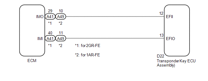
WIRING DIAGRAM
CAUTION / NOTICE / HINT
NOTICE:
- If the transponder key ECU assembly is replaced, register the key and
ECU communication ID (See page
.gif) ).
).
- If the ECM is replaced, register the ECU communication ID (See page
).
PROCEDURE
|
1. |
CHECK DTC OUTPUT |
(a) Clear the DTCs (See page ).
(b) Recheck for DTCs (See page ).
OK:
DTC B2799 is not output.
| OK | .gif) |
USE SIMULATION METHOD TO CHECK |
|
.gif)
|
2. |
RE-REGISTER ECU COMMUNICATION ID |
(a) Re-register the ECU communication ID (See page
).
|
|
3. |
CHECK DTC OUTPUT |
(a) Clear the DTCs (See page ).
(b) Recheck for DTCs (See page ).
OK:
DTC B2799 is not output.
| OK | |
END (ECU COMMUNICATION ID WAS NOT REGISTERED CORRECTLY) |
|
|
4. |
CHECK CONNECTION OF CONNECTOR |
(a) Turn the ignition switch off.
(b) Check that the connectors are properly connected to the ECM and transponder key ECU assembly.
OK:
Connectors are properly connected.
| NG | |
CONNECT CONNECTORS PROPERLY |
|
|
5. |
CHECK HARNESS AND CONNECTOR (TRANSPONDER KEY ECU - ECM) |
(a) Disconnect the transponder key ECU assembly connector.
|
(b) Disconnect the ECM connector. |
|
(c) Measure the resistance according to the value(s) in the table below.
Standard Resistance:
for 2GR-FE|
Tester Connection |
Condition |
Specified Condition |
|---|---|---|
|
D22-12 (EFII) - A41-29 (IMO) |
Always |
Below 1 Ω |
|
D22-13 (EFIO) - A41-40 (IMI) |
Always |
Below 1 Ω |
|
D22-12 (EFII) - Body ground |
Always |
10 kΩ or higher |
|
D22-13 (EFIO) - Body ground |
Always |
10 kΩ or higher |
|
A41-29 (IMO) - Body ground |
Always |
10 kΩ or higher |
|
A41-40 (IMI) - Body ground |
Always |
10 kΩ or higher |
|
Tester Connection |
Condition |
Specified Condition |
|---|---|---|
|
D22-12 (EFII) - A49-10 (IMO) |
Always |
Below 1 Ω |
|
D22-13 (EFIO) - A49-11 (IMI) |
Always |
Below 1 Ω |
|
D22-12 (EFII) - Body ground |
Always |
10 kΩ or higher |
|
D22-13 (EFIO) - Body ground |
Always |
10 kΩ or higher |
|
A49-10 (IMO) - Body ground |
Always |
10 kΩ or higher |
|
A49-11 (IMI) - Body ground |
Always |
10 kΩ or higher |
|
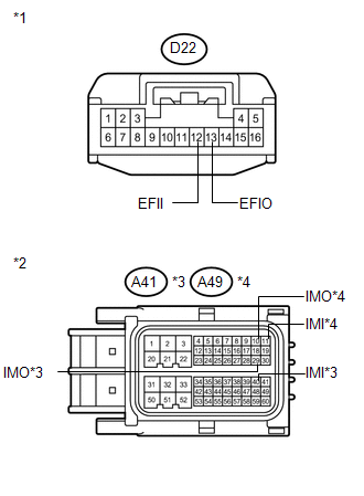
*1 |
Front view of wire harness connector (to Transponder Key ECU Assembly) |
|
*2 |
Front view of wire harness connector (to ECM) |
|
*3 |
for 2GR-FE |
|
*4 |
for 1AR-FE |
| NG | |
REPAIR OR REPLACE HARNESS OR CONNECTOR |
|
|
6. |
REPLACE ECM |
(a) Replace the ECM (See page for 2GR-FE,
for 1AR-FE).
|
|
7. |
REGISTER ECU COMMUNICATION ID |
(a) Register the ECU communication ID (See page
).
|
|
8. |
CHECK DTC OUTPUT |
(a) Clear the DTCs (See page ).
(b) Recheck for DTCs (See page ).
OK:
DTC B2799 is not output.
| OK | |
END (ECM WAS DEFECTIVE) |
| NG | |
REPLACE TRANSPONDER KEY ECU ASSEMBLY |
 Communication Malfunction No. 1 (B2797)
DESCRIPTION
This DTC is stored when an error occurs in communication between the transponder
key amplifier and the transponder key ECU assembly.
HINT:
Some noise is found in the communication lin ...
 Theft Deterrent System Communication Line High Fixation (B279A)
DESCRIPTION
If the communication line (EFIO-IMI) to the transponder key ECU assembly is stuck
high output (e.g. shorted to +B), the ECM stores this DTC.
DTC No.
DTC Detection ...
Other materials about Toyota Venza:
On-vehicle Inspection
ON-VEHICLE INSPECTION
CAUTION / NOTICE / HINT
CAUTION:
Be sure to follow the correct removal and installation procedures of the door
side airbag sensor.
PROCEDURE
1. INSPECT DOOR SIDE AIRBAG SENSOR (VEHICLE NOT INVOLVED IN COLLISION)
(a) Perform a diag ...
Vehicle Speed Sensor "A" (P0500)
DESCRIPTION
The speed sensor detects the wheel speed and sends the appropriate signals to
the skid control ECU.
The skid control ECU converts these wheel speed signals into a 4-pulse signal
and outputs it to the ECM via the combination meter. The ECM det ...
Radio Broadcast cannot be Received or Poor Reception
PROCEDURE
1.
CHECK NAVIGATION RECEIVER ASSEMBLY
(a) Check the radio automatic station search function.
(1) Check the radio automatic station search function by activating it.
Result
Proceed to
...

0.1703