Toyota Venza: Communication Malfunction No. 1 (B2797)
DESCRIPTION
This DTC is stored when an error occurs in communication between the transponder key amplifier and the transponder key ECU assembly.
HINT:
Some noise is found in the communication line.
|
DTC No. |
DTC Detection Condition |
Trouble Area |
|---|---|---|
|
B2797 |
Keys are positioned too close to each other, or noise occurs in communication line. |
|
CAUTION / NOTICE / HINT
NOTICE:
If the transponder key ECU assembly is replaced, register the key and ECU communication
ID (See page .gif) ).
).
PROCEDURE
|
1. |
CHECK KEY |
|
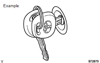
(a) Check whether the ignition key being used is near other ignition keys, as shown in the illustration. Also, check whether the key ring is in contact with the key grip. Result:
|
|
| B | .gif) |
GO TO STEP 3 |
|
.gif)
|
2. |
CHECK DTC OUTPUT |
(a) Separate the keys from each other or remove the key ring.
(b) Clear the DTCs (See page ).
(c) Insert a key into the ignition key cylinder and remove the key. Repeat for all the other keys of the vehicle.
OK:
No DTC is output.
| OK | |
END (KEYS WERE POSITIONED TOO CLOSE TO EACH OTHER) |
|
|
3. |
REPLACE TRANSPONDER KEY AMPLIFIER |
(a) Replace the transponder key amplifier (See page
).
|
|
4. |
CHECK ENGINE START |
(a) Check that the engine starts.
OK:
The engine starts.
| OK | |
END (TRANSPONDER KEY AMPLIFIER WAS DEFECTIVE) |
| NG | |
REPLACE TRANSPONDER KEY ECU ASSEMBLY |
 Theft Deterrent System Presence Detection (B279C)
DESCRIPTION
If an ECM that is incompatible with the engine immobiliser system is installed,
the ECM stores this DTC.
DTC No.
DTC Detection Condition
Trouble Area
...
 Engine Immobiliser System Malfunction (B2799)
DESCRIPTION
This DTC is stored when one of the following occurs: 1) the ECM detects errors
in its own communications with the transponder key ECU assembly; 2) the ECM detects
errors in the commun ...
Other materials about Toyota Venza:
Brake Switch "A" Circuit (P0571)
DESCRIPTION
When the brake pedal is depressed, the stop light switch assembly sends a signal
to the ECM. When the ECM receives this signal, it cancels the cruise control. The
fail-safe function operates to enable normal driving even if there is a malfunct ...
Fail-safe Chart
FAIL-SAFE CHART
HINT:
If the following conditions are detected while the cruise control is in operation,
the system clears the stored vehicle speed in the ECM and cancels the cruise control
operation.
Vehicle Condition
Auto Cancel ...
Inspection
INSPECTION
PROCEDURE
1. INSPECT INNER REAR VIEW MIRROR ASSEMBLY
(a) Inspect operation of the electrochromic inner mirror.
(1) Connect a positive (+) lead from the battery to terminal 1 and a negative
(-) lead to terminal 2.
(2) Press the AUTO switch.
...

0.1581