Toyota Venza: System Diagram
SYSTEM DIAGRAM
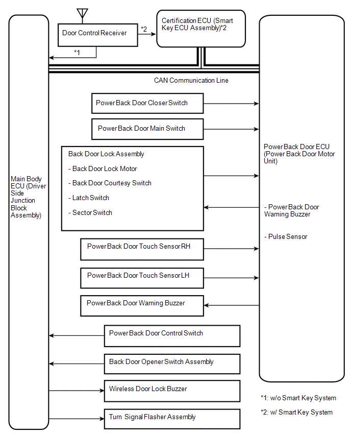 Communication Table
|
Sender |
Receiver |
Signal |
Line |
|---|---|---|---|
|
Main body ECU (Driver side junction block assembly) |
Power back door ECU (Power back door motor unit) |
|
CAN |
|
Power back door ECU (Power back door motor unit) |
Main body ECU (Driver side junction block assembly) |
|
CAN |
|
Certification ECU |
Main body ECU (Driver side junction block assembly) |
Transmitter switch signal |
CAN |
 System Description
SYSTEM DESCRIPTION
1. POWER BACK DOOR SYSTEM DESCRIPTION
(a) The power back door system controls the power back door by automatically
opening and closing the power back door with a motor.
(1) The ...
 How To Proceed With Troubleshooting
CAUTION / NOTICE / HINT
HINT:
Use the following procedures to troubleshoot the power back door system.
*: Use the Techstream.
PROCEDURE
1.
VEHICLE BROUG ...
Other materials about Toyota Venza:
Power Source Mode does not Change to ON (IG)
DESCRIPTION
When the engine switch is pushed with the electrical key in the cabin, the power
management control ECU receives signals to change the power source mode.
HINT:
To allow use of the Techstream to inspect the push-button start function when
the ...
Disassembly
DISASSEMBLY
CAUTION / NOTICE / HINT
NOTICE:
When disassembling the multiplex network door ECU, eliminate static electricity
by touching the vehicle body to prevent the components from being damaged.
PROCEDURE
1. REMOVE MULTIPLEX NETWORK DOOR ECU
...
Inspection
INSPECTION
PROCEDURE
1. INSPECT VACUUM SWITCHING VALVE ASSEMBLY (for ACIS)
(a) Measure the resistance according to the value(s) in the table below.
Text in Illustration
*1
Body Ground
Stan ...

0.1611