Toyota Venza: Door Control Switch
Components
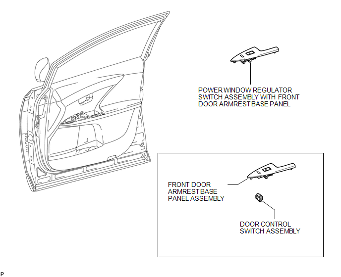
COMPONENTS
ILLUSTRATION
Inspection
INSPECTION
PROCEDURE
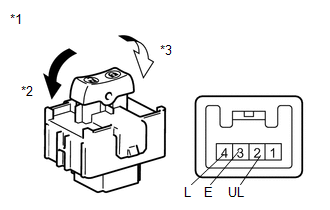
1. INSPECT DOOR CONTROL SWITCH ASSEMBLY
|
(a) Measure the resistance according to the value(s) in the table below. Standard Resistance:
If the result is not as specified, replace the door control switch assembly |
|
Removal
REMOVAL
PROCEDURE
1. REMOVE POWER WINDOW REGULATOR SWITCH ASSEMBLY WITH FRONT DOOR ARMREST BASE PANEL
.gif)
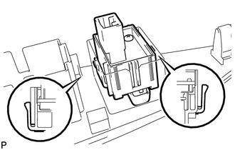
2. REMOVE DOOR CONTROL SWITCH ASSEMBLY
|
(a) Disengage the 2 claws and remove the door control switch assembly. |
|
Installation
INSTALLATION
PROCEDURE
1. INSTALL DOOR CONTROL SWITCH ASSEMBLY
|
(a) Engage the 2 claws and install the door control switch assembly. |
|
.png)
2. INSTALL POWER WINDOW REGULATOR SWITCH ASSEMBLY WITH FRONT DOOR ARMREST BASE PANEL
.gif)
 Installation
INSTALLATION
PROCEDURE
1. INSTALL DOOR CONTROL RECEIVER
(a) Install the door control receiver with the bolt.
(b) Connect the connector.
2 ...
 Door Control Transmitter(w/ Smart Key System)
Components
COMPONENTS
ILLUSTRATION
Removal
REMOVAL
PROCEDURE
1. REMOVE TRANSMITTER BATTERY
Inspection
INSPECTION
PROCEDURE
1. INSPECT DOOR CONTROL TRANSMITTER
(a) Inspect operati ...
Other materials about Toyota Venza:
Auto Up Operation does not Fully Close Power Window (Jam Protection Function
is Activated)
DESCRIPTION
If a door glass or a power window regulator motor assembly does not operate smoothly,
the jam protection function may be triggered automatically, resulting in the auto
up function being unable to fully close the window.
HINT:
This symptom ma ...
Inspection
INSPECTION
PROCEDURE
1. INSPECT FRONT POWER SEAT SWITCH LH (w/o Seat Position Memory System)
(a) Measure the resistance between the terminals when each switch is
operated.
Standard Resistance:
Slide Switch
Tester Co ...
Precaution
PRECAUTION
NOTICE:
When disconnecting the cable from the negative (-) battery terminal, initialize
the following systems after the cable is reconnected.
System Name
See Procedure
Back Door Closer System
...

0.1309