Toyota Venza: Disassembly
DISASSEMBLY
PROCEDURE
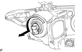
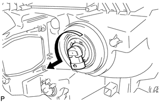
1. REMOVE NO. 2 HEADLIGHT BULB (for Halogen Headlight)
|
(a) Turn the No. 2 headlight bulb in the direction indicated by the arrow shown in the illustration, and remove it. NOTICE: Do not touch the bulb glass. |
|
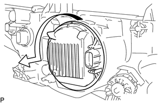
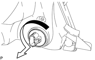
2. REMOVE LIGHT CONTROL ECU (for HID Headlight)
|
(a) Turn the light control ECU in the direction indicated by the arrow shown in the illustration, and disconnect it. NOTICE:
|
|
|
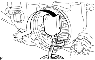
(b) Turn the socket of the light control ECU in the direction indicated by the arrow shown in the illustration, and remove it. NOTICE: Do not pull the light control ECU with the socket connected. |
|
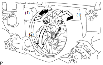
3. REMOVE DISCHARGE HEADLIGHT BULB (for HID Headlight)
|
(a) Release the set spring as shown in the illustration and remove the discharge headlight bulb. NOTICE: Do not touch the bulb glass. |
|
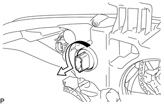
4. REMOVE NO. 1 HEADLIGHT BULB (for Halogen Headlight)
|
(a) Turn the No. 1 headlight bulb in the direction indicated by the arrow shown in the illustration, and remove it. NOTICE: Do not touch the bulb glass. |
|
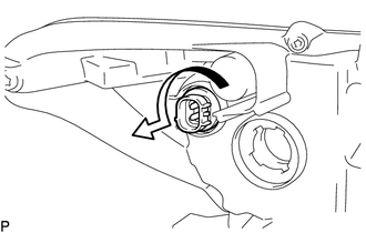
5. REMOVE FRONT TURN SIGNAL LIGHT BULB
(a) for Halogen Headlight:
|
(1) Turn the front turn signal light socket with the front turn signal light bulb in the direction indicated by the arrow shown in the illustration, and remove them as a unit. |
|
(b) for HID Headlight:
|
(1) Turn the front turn signal light socket with the front turn signal light bulb in the direction indicated by the arrow shown in the illustration, and remove them as a unit. |
|
(c) Remove the front turn signal light bulb from the front turn signal light socket.
6. REMOVE FRONT SIDE MARKER LIGHT BULB
|
(a) Turn the front side marker light socket with the front side marker light bulb in the direction indicated by the arrow shown in the illustration, and remove them as a unit. |
|
(b) Remove the front side marker light bulb from the front side marker light socket.
 Components
COMPONENTS
ILLUSTRATION
ILLUSTRATION
...
 Removal
REMOVAL
CAUTION / NOTICE / HINT
HINT:
Use the same procedure for the RH and LH sides.
The procedure described below is for the LH side.
PROCEDURE
1. PRECAUTION (for HID Headligh ...
Other materials about Toyota Venza:
Adjustment
ADJUSTMENT
CAUTION / NOTICE / HINT
CAUTION:
Before adjusting the door positions of vehicles equipped with side and curtain
shield airbags, be sure to disconnect the battery. After adjustment, check that
the SRS warning light is operating normally and ...
Installation
INSTALLATION
PROCEDURE
1. INSTALL DOOR CONTROL RECEIVER
(a) Install the door control receiver with the bolt.
(b) Connect the connector.
2. INSTALL ROOF SIDE INNER GARNISH ASSEMBLY RH
HINT:
Use th ...
Automatic transmission
Select a shift position appropriate for the driving conditions.
- Shifting the shift lever
Vehicles with smart key system:
While the “ENGINE START STOP” switch is in IGNITION ON mode, depress the brake
pedal and move the shift lever.
Vehicles ...

0.1587