Toyota Venza: Components
COMPONENTS
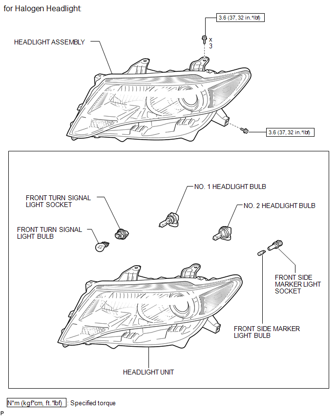
ILLUSTRATION
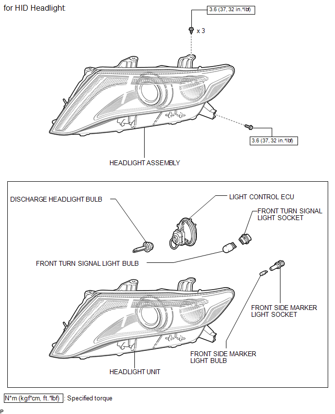
ILLUSTRATION

 Disassembly
DISASSEMBLY
PROCEDURE
1. REMOVE NO. 2 HEADLIGHT BULB (for Halogen Headlight)
(a) Turn the No. 2 headlight bulb in the direction indicated by the arrow
shown in the illustration, and ...
Other materials about Toyota Venza:
Open in CAN Main Bus Line
DESCRIPTION
There may be an open circuit in the CAN bus main wire and/or the DLC3 branch
wire when the resistance between terminals 6 (CANH) and 14 (CANL) of the DLC3 is
70 Ω or higher.
Symptom
Trouble Area
Resista ...
Installation
INSTALLATION
PROCEDURE
1. INSTALL INSTRUMENT PANEL WIRE ASSEMBLY
(a) Connect the vent hole connector of the instrument panel wire to the
front passenger airbag assembly.
Text in Illustration
*1
Vent Hol ...
Inspection
INSPECTION
PROCEDURE
1. INSPECT CHARCOAL CANISTER ASSEMBLY
(a) Visually check the charcoal canister assembly.
(1) Visually check the charcoal canister assembly for cracks or damage.
If cracks or damage are found, replace the charcoal canister ...

0.1326