Toyota Venza: Console Box Light
Components
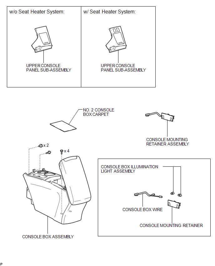
COMPONENTS
ILLUSTRATION
Removal
REMOVAL
PROCEDURE
1. REMOVE UPPER CONSOLE PANEL SUB-ASSEMBLY (w/o Seat Heater System)
.gif)
2. REMOVE UPPER CONSOLE PANEL SUB-ASSEMBLY (w/ Seat Heater System)
3. REMOVE NO. 2 CONSOLE BOX CARPET
4. REMOVE CONSOLE BOX ASSEMBLY
5. REMOVE CONSOLE MOUNTING RETAINER ASSEMBLY
6. REMOVE CONSOLE BOX WIRE
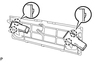
7. REMOVE CONSOLE BOX ILLUMINATION LIGHT ASSEMBLY
|
(a) Disengage the 4 claws and remove the 2 console box illumination light assemblies. |
|
Inspection
INSPECTION
PROCEDURE
1. INSPECT CONSOLE BOX ILLUMINATION LIGHT ASSEMBLY
|
(a) Connect a positive (+) lead from the battery to terminal 2 and a negative (-) lead to terminal 1. |
|
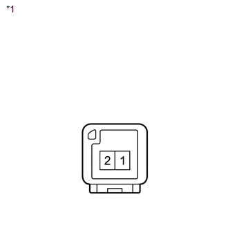
(b) Check that the console box illumination light comes on.
OK:
Console box illumination light comes on.
Text in Illustration|
*1 |
Component without harness connected (Console Box Illumination Light Assembly) |
If the result is not as specified, replace the console box illumination light assembly.
Installation
INSTALLATION
PROCEDURE
1. INSTALL CONSOLE BOX ILLUMINATION LIGHT ASSEMBLY
|
(a) Engage the 4 claws to install the 2 console box illumination light assemblies. |
|
.png)
2. INSTALL CONSOLE BOX WIRE
.gif)
3. INSTALL CONSOLE MOUNTING RETAINER ASSEMBLY
4. INSTALL CONSOLE BOX ASSEMBLY
5. INSTALL NO. 2 CONSOLE BOX CARPET
6. INSTALL UPPER CONSOLE PANEL SUB-ASSEMBLY (w/o Seat Heater System)
7. INSTALL UPPER CONSOLE PANEL SUB-ASSEMBLY (w/ Seat Heater System)
 Back Door Courtesy Switch
Components
COMPONENTS
ILLUSTRATION
Removal
REMOVAL
PROCEDURE
1. REMOVE BACK DOOR PANEL TRIM ASSEMBLY
2. REMOVE BACK DOOR LOCK ASSEMBLY
(a) Disconnect the connector.
...
 Door Courtesy Light
Components
COMPONENTS
ILLUSTRATION
Removal
REMOVAL
PROCEDURE
1. REMOVE COURTESY LIGHT ASSEMBLY
(a) Using a screwdriver wrapped with protective tape, disengage the claw.
Text ...
Other materials about Toyota Venza:
Inspection
INSPECTION
PROCEDURE
1. INSPECT PAD LINING THICKNESS
(a) Using a ruler, measure the pad lining thickness.
Text in Illustration
*1
Ruler
Standard thickness of a new pad:
10.0 mm (0.394 ...
Problem Symptoms Table
PROBLEM SYMPTOMS TABLE
HINT:
Use the table below to help determine the cause of problem symptoms.
If multiple suspected areas are listed, the potential causes of the symptoms
are listed in order of probability in the "Suspected Area" ...
Installation
INSTALLATION
PROCEDURE
1. INSTALL FRONT SUSPENSION MEMBER BODY MOUNTING REAR CUSHION LH
(a) Temporarily install a new front suspension member body mounting rear
cushion LH while confirming the installation direction.
NOTICE:
Position th ...

0.1279