Toyota Venza: Removal
REMOVAL
PROCEDURE
1. REMOVE PARKING BRAKE PEDAL ASSEMBLY
HINT:
Refer to the instructions for Removal of the parking brake pedal assembly (See
page .gif) ).
).
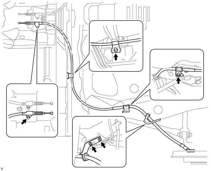
2. REMOVE NO. 1 PARKING BRAKE CABLE ASSEMBLY
|
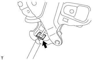
(a) Remove the clip. |
|
|
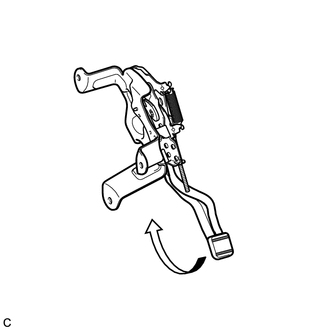
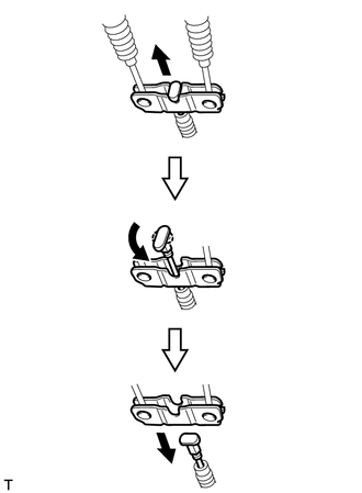
(b) Depress the parking brake pedal. |
|
|
(c) Pull up the parking brake pedal claw and remove the No. 1 parking brake cable assembly from the parking brake pedal assembly. |
|
3. REMOVE REAR WHEEL
4. REMOVE NO. 4 PARKING BRAKE CABLE ASSEMBLY
|
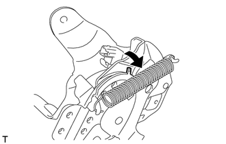
(a) Slide the rubber boot as shown in the illustration. |
|
|
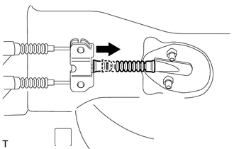
(b) Separate the No. 4 parking brake cable assembly from the parking brake equalizer as shown in the illustration. |
|
|
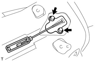
(c) Remove the 2 bolts and No. 4 parking brake cable assembly. |
|
5. REMOVE PARKING BRAKE EQUALIZER
|
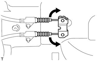
(a) Move the No. 2 parking brake cable assembly and No. 3 parking brake cable assembly as shown in the illustration to remove the parking brake equalizer. |
|
6. REMOVE NO. 2 PARKING BRAKE SHOE ASSEMBLY WITH PARKING BRAKE SHOE LEVER
HINT:
Refer to the instructions for Removal of the No. 2 parking brake shoe assembly
with parking brake shoe lever (See page ).
7. REMOVE NO. 3 PARKING BRAKE CABLE ASSEMBLY
|
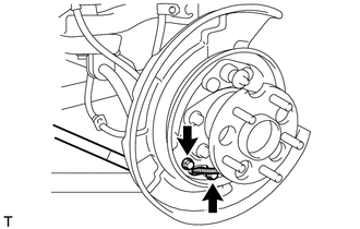
(a) Remove the 2 bolts and separate the No. 3 parking brake cable assembly from the backing plate. |
|
(b) Remove the bolt, 4 nuts and the No. 3 parking brake cable assembly.
8. REMOVE NO. 2 PARKING BRAKE CABLE ASSEMBLY
HINT:
Use the same procedure as for the No. 3 parking brake cable assembly.
 Components
COMPONENTS
ILLUSTRATION
ILLUSTRATION
ILLUSTRATION
...
 Installation
INSTALLATION
PROCEDURE
1. INSTALL NO. 3 PARKING BRAKE CABLE ASSEMBLY
(a) Install the No. 3 parking brake cable assembly with the bolt and 4 nuts.
Torque:
Nut (A) :
5.4 N·m {55 kgf·cm, 48 i ...
Other materials about Toyota Venza:
Adjustment
ADJUSTMENT
CAUTION / NOTICE / HINT
HINT:
Centering bolts are used to mount the hood hinge and hood lock. The
hood and hood lock cannot be adjusted with the centering bolts installed.
Substitute the centering bolts with standard bolts when ...
If a warning message is displayed
The multi-information display shows warnings of system malfunctions or incorrectly
performed operations. When a message is shown, perform corrections as indicated
in the message.
1. Master warning light
The master warning light comes on or flashes when ...
Lost Communication with Automatic High Beam Sensor (B2432)
DESCRIPTION
Refer to DTC B2432 (Lighting system) (See page
).
DTC No.
DTC Detection Condition
Trouble Area
B2432
Malfunction in LIN communication system
Inner rear view mirr ...

0.1562