Toyota Venza: Diagnosis Circuit
DESCRIPTION
This circuit is used to read the DTCs that are output from the transponder key ECU assembly with the Techstream.
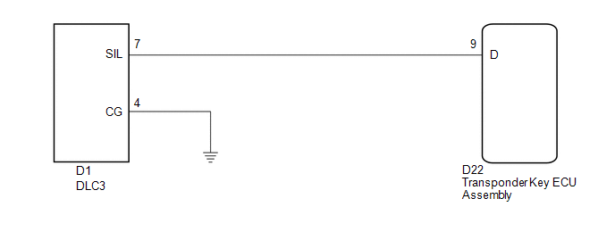
WIRING DIAGRAM
CAUTION / NOTICE / HINT
NOTICE:
If the transponder key ECU assembly is replaced, register the key and ECU communication
ID (See page .gif) ).
).
PROCEDURE
|
1. |
CHECK HARNESS AND CONNECTOR (DLC3 - TRANSPONDER KEY ECU AND BODY GROUND) |
|
(a) Disconnect the transponder key ECU assembly connector. |
|
(b) Measure the resistance according to the value(s) in the table below.
Standard Resistance:
|
Tester Connection |
Condition |
Specified Condition |
|---|---|---|
|
D22-9 (D) - D1-7 (SIL) |
Always |
Below 1 Ω |
|
D1-4 (CG) - Body ground |
Always |
Below 1 Ω |
|
D22-9 (D) - Body ground |
Always |
10 kΩ or higher |
|
D1-7 (SIL)- Body ground |
Always |
10 kΩ or higher |
|
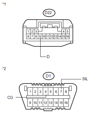
*1 |
Front view of wire harness connector (to Transponder Key ECU Assembly) |
|
*2 |
Front view of wire harness connector (to DLC3) |
| OK | .gif) |
REPLACE TRANSPONDER KEY ECU ASSEMBLY |
| NG | |
REPAIR OR REPLACE HARNESS OR CONNECTOR |
 ECU Power Source Circuit
DESCRIPTION
This circuit provides power to operate the transponder key ECU assembly.
WIRING DIAGRAM
CAUTION / NOTICE / HINT
NOTICE:
If the transponder key ECU assembly is replaced, register the ...

Other materials about Toyota Venza:
Removal
REMOVAL
CAUTION / NOTICE / HINT
NOTICE:
Release the vacuum from the booster by depressing the brake pedal several times.
Then remove the brake master cylinder from the brake booster.
PROCEDURE
1. DRAIN BRAKE FLUID
NOTICE:
If brake fluid leaks onto any ...
Removal
REMOVAL
PROCEDURE
1. DISCONNECT CABLE FROM NEGATIVE BATTERY TERMINAL
NOTICE:
When disconnecting the cable, some systems need to be initialized after the cable
is reconnected (See page ).
2. REMOVE UPPER CONSOLE PANEL SUB-ASSEMBLY (w/o Seat Heater Syste ...
Removal
REMOVAL
PROCEDURE
1. REMOVE COOL AIR INTAKE DUCT SEAL
(a) Using a clip remover, remove the 12 clips and cool air intake duct
seal.
2. REMOVE RADIATOR GRILLE
3. REMOVE FRONT BUMPER ASSEMBLY
...

0.1817