Toyota Venza: Components
COMPONENTS
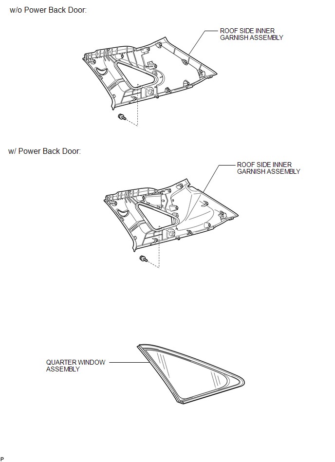
ILLUSTRATION
.png)
ILLUSTRATION
.png)
ILLUSTRATION
.png)
ILLUSTRATION
.png)
ILLUSTRATION
.png)
ILLUSTRATION

 Removal
REMOVAL
CAUTION / NOTICE / HINT
HINT:
The front side fix window assembly can be reused. When installing the
window, if any of the clips on the quarter window glass are broken, butyl
...
Other materials about Toyota Venza:
Reassembly
REASSEMBLY
PROCEDURE
1. INSTALL FUEL PUMP ASSEMBLY WITH FILTER
HINT:
Perform "Inspection After Repair" after replacing the fuel pump (See page
).
(a) Apply gasoline to a new O-ring. Then install the O-ring and spacer
to the fuel ...
Short in Front Passenger Side Squib 2nd Step Circuit (B1815/54-B1818/54)
DESCRIPTION
The front passenger side squib 2nd step circuit consists of the center airbag
sensor assembly and front passenger airbag assembly.
The center airbag sensor assembly uses this circuit to deploy the airbag when
deployment conditions are met.
T ...
Front Occupant Classification Sensor RH Circuit Malfunction (B1781)
DESCRIPTION
The front occupant classification sensor RH circuit consists of the occupant
classification ECU and front occupant classification sensor RH.
DTC B1781 is recorded when a malfunction is detected in the front occupant classification
sensor RH c ...

0.1306