Toyota Venza: Brake Line
Precaution
PRECAUTION
1. TROUBLESHOOTING PRECAUTION
NOTICE:
- Since the brake lines are critical safety related parts, be sure to disassemble and inspect the components if a brake fluid leak is found. If any abnormality is found, replace the component with a new one.
- When removing brake components, cover the brake line connections to prevent foreign matter such as dust or dirt from entering the lines.
- Do not damage or deform the brake lines during the removal and installation procedures.
- When installing a grommet to the body, ensure that the brake line passes through the center of the grommet.
- When installing a brake line or flexible hose, ensure that they are free from twists or bends.
- If the metal end of a flexible hose does not match the groove on the bracket, twist the hose slightly to insert it.
- Flexible hoses must be free from shock absorber oil, grease, etc.
- When installing a brake line to a plastic clamp, ensure that the brake line is not loose or pinched.
- Do not reuse any clips or plastic clamps removed from a flexible hose.
- After installing a brake line or flexible hose, ensure that they do not interfere with any other components or body.
- Do not allow brake fluid on any painted vehicle body surface. If brake fluid leaks onto any painted surface, immediately wash it off.
- When disconnecting and connecting a flexible hose and brake line:
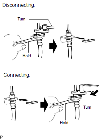
- Hold the flexible hose with a wrench and disconnect the brake tube using a union nut wrench without deforming the tube.
- Remove the clip and disconnect the flexible hose.
- Secure the flexible hose with a new clip. At this time, be sure to securely install the clip.
- Connect the brake tube using a union nut wrench without deforming the tube.
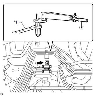
- When connecting a brake line and way:
 Text in illustration
*1
Hold
*2
Turn
- Support the way to prevent the brake tubes from being deformed and connect each brake tube using a union nut wrench.
- Support the way to prevent the brake lines from being deformed and install the way to the vehicle body with the bolt.
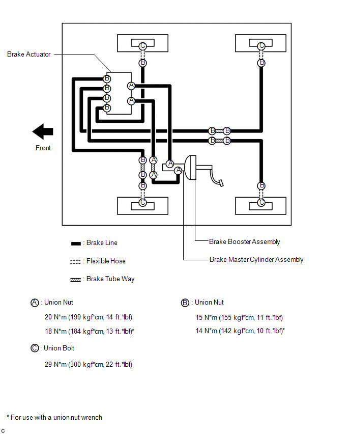
System Diagram
SYSTEM DIAGRAM
 Bleeding
BLEEDING
CAUTION / NOTICE / HINT
NOTICE:
Do not allow brake fluid to adhere to any painted surface such as the
vehicle body. If brake fluid leaks onto any painted surface, immediately
...

Other materials about Toyota Venza:
Reassembly
REASSEMBLY
PROCEDURE
1. INSTALL GENERATOR ROTOR ASSEMBLY
(a) Place the generator drive end frame on the generator pulley.
(b) Install the generator rotor to the generator drive end frame.
...
Removal
REMOVAL
PROCEDURE
1. REMOVE FRONT SEAT HEADREST ASSEMBLY
2. REMOVE FRONT SEAT REAR OUTER TRACK COVER
3. REMOVE FRONT SEAT REAR INNER TRACK COVER
4. REMOVE FRONT SEAT ASSEMBLY
5. REMOVE RECLINING POWER SEAT SWITCH KNOB
6. REMOVE SLIDE AND VER ...
Throttle Actuator Control Throttle Body Range / Performance (P2119)
DESCRIPTION
The electronic throttle control system is composed of the throttle actuator,
throttle position sensor, accelerator pedal position sensor, and ECM. The ECM operates
the throttle actuator to regulate the throttle valve in response to driver inpu ...

0.1589