Toyota Venza: ECU Power Source Circuit
DESCRIPTION
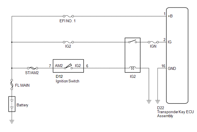
This circuit provides power to operate the transponder key ECU assembly.
WIRING DIAGRAM
CAUTION / NOTICE / HINT
NOTICE:
If the transponder key ECU assembly is replaced, register the key and ECU communication
ID (See page .gif) ).
).
PROCEDURE
|
1. |
CHECK HARNESS AND CONNECTOR (TRANSPONDER KEY ECU - BATTERY AND BODY GROUND) |
|
(a) Disconnect the transponder key ECU assembly connector. |
|
(b) Measure the voltage and resistance according to the value(s) in the table below.
Standard Voltage:
|
Tester Connection |
Condition |
Specified Condition |
|---|---|---|
|
D22-1 (+B) - Body ground |
Always |
11 to 14 V |
|
D22-2 (IG) - Body ground |
Ignition switch off |
Below 1 V |
|
D22-2 (IG) - Body ground |
Ignition switch ON |
11 to 14 V |
Standard Resistance:
|
Tester Connection |
Condition |
Specified Condition |
|---|---|---|
|
D22-16 (GND) - Body ground |
Always |
Below 1 Ω |
|
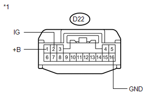
*1 |
Front view of wire harness connector (to Transponder Key ECU Assembly) |
| OK | .gif) |
PROCEED TO NEXT SUSPECTED AREA SHOWN IN PROBLEM SYMPTOMS TABLE |
| NG | |
REPAIR OR REPLACE HARNESS OR CONNECTOR, OR REPLACE FUSE |
 Security Indicator Light Circuit
DESCRIPTION
The security indicator light blinks continuously due to a continuous signal received
from the transponder key ECU assembly while in the armed state.
WIRING DIAGRAM
CAUTION / NOTICE ...
 Diagnosis Circuit
DESCRIPTION
This circuit is used to read the DTCs that are output from the transponder key
ECU assembly with the Techstream.
WIRING DIAGRAM
CAUTION / NOTICE / HINT
NOTICE:
If the transponder ...
Other materials about Toyota Venza:
How To Proceed With Troubleshooting
CAUTION / NOTICE / HINT
HINT:
Use the following procedures to troubleshoot the power back door system.
*: Use the Techstream.
PROCEDURE
1.
VEHICLE BROUGHT TO WORKSHOP
NEXT
...
System Description
SYSTEM DESCRIPTION
1. DESCRIPTION
(a) The steering lock system locks/unlocks the steering when by activating the
steering lock bar with a motor. The steering lock ECU (steering lock actuator assembly)
activates the motor based on signals from the certifi ...
System Description
SYSTEM DESCRIPTION
1. OUTLINE OF THEFT DETERRENT SYSTEM
The theft deterrent system can be set by locking the doors using the
transmitter or key, or by opening and closing the doors (for details, refer
to Active Arming Mode or Passive Arming Mo ...

0.1303