Toyota Venza: Rear seats
Seatback angle adjustment lever
Pull up the lever until the lock is completely released.
Folding down the rear seatbacks
- Before folding down the rear seatbacks
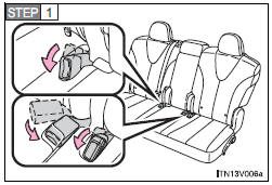
Stow the seat belt buckles and lower the head restraints to the lowest position.
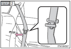
Pass the outer seat belts and plates through the seat belt hangers.
This prevents the shoulder belt from being damaged.
Make sure that the seat belts are removed from the hangers before using them.
- Folding down the rear seatbacks
► From inside
Fold down the seatback while pulling the seatback angle adjustment lever.
Pull up the lever until the lock is completely released.
► From outside
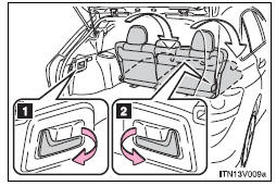
Pull the lever.
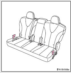
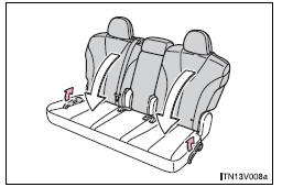
1. For left side rear seatback 2. For right side and center rear seatback
CAUTION
- Seat adjustment
Do not recline the seat more than necessary when the vehicle is in motion, to reduce the risk of sliding under the lap belt. If the seat is too reclined, the lap belt may slide past the hips and apply restraint forces directly to the abdomen or your neck may contact the shoulder belt, increasing the risk of death or serious injury in the event of an accident.
- Before folding down a rear seat
Do not fold down a rear seat when there are passengers sitting in the rear seats or when there is luggage placed on the rear seats.
- When returning the seatbacks to their original position
Observe the following precautions. Failure to do so may result in death or serious injury.
• Be careful not to get your hands pinched in the seat.
• Make sure the seatbacks are securely locked by lightly rocking it back and forth.
• Check that the seat belts are not twisted or caught under the seat.
• Arrange the seat belts in the proper positions for ready use.
NOTICE
- When folding down the rear seatbacks
The seat belts and buckles must be stowed.
 Front seats
► Power seat
1. Seat position fore/aft control switch
2. Seatback angle control switch
3. Seat cushion (front) angle control switch (driver’s side only)
4. Vertical height control switch ...
 Driving position memory
Your preferred driving position (the position of the driver’s seat and angle
of the outside rear view mirrors) can be memorized and recalled by pressing a button.
It is also possible to set this ...
Other materials about Toyota Venza:
Crankshaft Position Sensor "A" Circuit (P0335,P0339)
DESCRIPTION
The crankshaft position sensor system consists of a crank angle sensor plate
and a pickup coil.
The sensor plate has 34 teeth and is installed on the crankshaft. The pickup
coil is made of wound copper wire, an iron core and magnet. The senso ...
Installation
INSTALLATION
PROCEDURE
1. INSTALL COOLER CONDENSER ASSEMBLY
(a) Install the cooler condenser assembly with the 4 bolts.
Torque:
6.0 N·m {61 kgf·cm, 53 in·lbf}
HINT:
If the condenser is replaced with a new one, add compressor oil t ...
Power Seat Power Easy Access System Function does not Operate
DESCRIPTION
When the ignition switch is off and shift lever is in P, the power seat slides
rearward when the seat belt tongue plate is disengaged from the front seat inner
belt assembly LH (auto away function). Also the power seat slides forward when the ...

0.1581