Toyota Venza: Diagnosis Circuit
DESCRIPTION
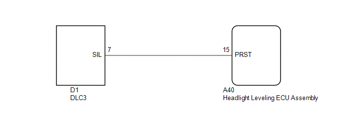
The headlight leveling ECU assembly outputs DTC information to the Techstream via this circuit.
WIRING DIAGRAM
PROCEDURE
|
1. |
CHECK HARNESS AND CONNECTOR (DLC3 - HEADLIGHT LEVELING ECU ASSEMBLY) |
(a) Disconnect the A40 headlight leveling ECU assembly connector.
(b) Measure the resistance according to the value(s) in the table below.
Standard Resistance:
|
Tester Connection |
Condition |
Specified Condition |
|---|---|---|
|
A40-15 (PRST) - D1-7 (SIL) |
Always |
Below 1 Ω |
|
A40-15 (PRST) - Body ground |
Always |
10 kΩ or higher |
| OK | .gif) |
PROCEED TO NEXT SUSPECTED AREA SHOWN IN PROBLEM SYMPTOMS TABLE |
| NG | |
REPAIR OR REPLACE HARNESS OR CONNECTOR |
 LVL Terminal Circuit
DESCRIPTION
By connecting terminals LVL and CG of the DLC3, the headlight leveling
ECU assembly initializes the height control sensor signal.
WIRING DIAGRAM
PROCEDURE
...

Other materials about Toyota Venza:
Operation Check
OPERATION CHECK
1. CHECK POWER SEAT FUNCTION
(a) Check the basic functions.
Text in Illustration
*1
Slide Function
*2
Front Vertical Function
*3
Lifter Function
...
Inspection
INSPECTION
PROCEDURE
1. INSPECT FUEL INJECTOR ASSEMBLY
(a) Measure the resistance according to the value(s) in the table below.
Standard Resistance:
Tester Connection
Condition
Specified C ...
Door Mirror Foot Light Circuit
DESCRIPTION
The main body ECU (driver side junction block assembly) controls the door mirror
foot lights.
WIRING DIAGRAM
1. w/o Seat Position Memory:
2. w/ Seat Position Memory:
PROCEDURE
1.
CHECK VEHICLE CONDITION
...

0.1194