Toyota Venza: Check Mode Procedure
CHECK MODE PROCEDURE
HINT:
Techstream only:
Compared to normal mode, check mode is more sensitive to malfunctions. Therefore, check mode can detect malfunctions that cannot be detected in normal mode.
NOTICE:
All the stored DTCs and freeze frame data are cleared if: 1) the ECM is changed from normal mode to check mode or vice versa; or 2) the ignition switch is turned from ON to ACC or off while in check mode. Before changing modes, always check and note any DTCs and freeze frame data.
1. CHECK MODE PROCEDURE
(a) Check and ensure the following conditions:
(1) Battery voltage is 11 V or higher.
(2) Throttle valve is fully closed.
(3) Shift lever is in P or N.
(4) A/C switch is off.
(b) Turn the ignition switch off.
(c) Connect the Techstream to the DLC3.
(d) Turn the ignition switch to ON.
(e) Turn the Techstream on.
(f) Enter the following menus: Powertrain / Engine / Utility / Check Mode.
(g) Switch the ECM from normal mode to check mode.
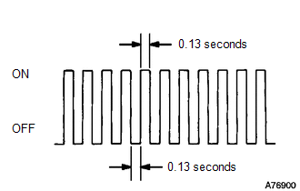
(h) Check that the MIL flashes as shown in the illustration.
(i) Start the engine.
(j) Check that the MIL turns off.
(k) Simulate the conditions of the malfunction described by the customer.
(l) Check DTCs and freeze frame data using the Techstream.
 Dtc Check / Clear
DTC CHECK / CLEAR
NOTICE:
When the diagnosis system is changed from normal mode to check mode or vice versa,
all DTCs and freeze frame data recorded in normal mode are cleared. Before changing
m ...
 Freeze Frame Data
FREEZE FRAME DATA
1. DESCRIPTION
The ECM records vehicle and driving condition information as freeze
frame data the moment a DTC is stored. When troubleshooting, freeze frame
data can ...
Other materials about Toyota Venza:
Fog light switch
The fog lights improve visibility in difficult driving conditions, such as
in rain or fog. The fog lights can be used when the headlights are on low beam.
Type A
1. Off
2. On
Type B
1. Off
2. On
Wiper intervals can be adjusted for intermittent ...
Initialization
INITIALIZATION
1. INITIALIZE SLIDING ROOF ECU (SLIDING ROOF DRIVE GEAR SUB-ASSEMBLY)
NOTICE:
When the sliding roof glass, sliding roof housing or sliding roof ECU
(sliding roof drive gear sub-assembly) is replaced or removed and installed,
t ...
Installation
INSTALLATION
PROCEDURE
1. INSTALL NO. 1 ULTRASONIC SENSOR RETAINER
(a) Engage the 2 claws to install the No. 1 ultrasonic sensor retainer
to the rear bumper assembly.
Text in Illustration
*A
LH Side
...

0.1621