Toyota Venza: LVL Terminal Circuit
DESCRIPTION
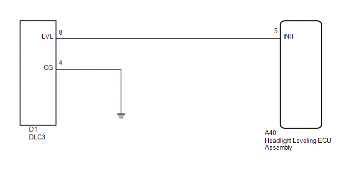
- By connecting terminals LVL and CG of the DLC3, the headlight leveling ECU assembly initializes the height control sensor signal.
WIRING DIAGRAM
PROCEDURE
|
1. |
CHECK HARNESS AND CONNECTOR (DLC3 - HEADLIGHT LEVELING ECU ASSEMBLY) |
|
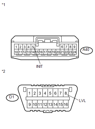
(a) Disconnect the A40 headlight leveling ECU assembly connector. |
|
(b) Measure the resistance according to the value(s) in the table below.
Standard Resistance:
|
Tester Connection |
Condition |
Specified Condition |
|---|---|---|
|
A40-5 (INIT) - D1-8 (LVL) |
Always |
Below 1 Ω |
|
A40-5 (INIT) - Body ground |
Always |
10 kΩ or higher |
|
*1 |
Front view of wire harness connector (to Headlight Leveling ECU Assembly) |
|
*2 |
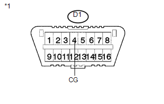
DLC3 |
| NG | .gif) |
REPAIR OR REPLACE HARNESS OR CONNECTOR |
|
.gif)
|
2. |
CHECK HARNESS AND CONNECTOR (DLC3 - BODY GROUND) |
|
(a) Measure the resistance according to the value(s) in the table below. Standard Resistance:
|
|
| OK | |
PROCEED TO NEXT SUSPECTED AREA SHOWN IN PROBLEM SYMPTOMS TABLE |
| NG | |
REPAIR OR REPLACE HARNESS OR CONNECTOR |
 Inner Rear View Mirror Power Source Circuit
DESCRIPTION
This circuit detects the state of the ignition switch, and sends it to the inner
rear view mirror assembly.
WIRING DIAGRAM
CAUTION / NOTICE / HINT
NOTICE:
Inspect the fuses for ci ...
 Diagnosis Circuit
DESCRIPTION
The headlight leveling ECU assembly outputs DTC information to the Techstream
via this circuit.
WIRING DIAGRAM
PROCEDURE
1.
CHECK HARNESS AND CONNECTOR (DLC3 ...
Other materials about Toyota Venza:
Front Passenger Side Door ECU Communication Stop (B2322)
DESCRIPTION
This DTC is stored when LIN communication between the power window regulator
motor assembly (for front passenger side) and main body ECU (driver side junction
block assembly) stops for more than 10 seconds.
DTC No.
DTC D ...
Problem Symptoms Table
PROBLEM SYMPTOMS TABLE
HINT:
Use the table below to help determine the cause of problem symptoms.
If multiple suspected areas are listed, the potential causes of the symptoms
are listed in order of probability in the "Suspected Area" ...
How To Proceed With Troubleshooting
CAUTION / NOTICE / HINT
HINT:
Use the following procedure listed to troubleshoot the Active Torque
Control 4WD system.
*: Use the Techstream.
PROCEDURE
1.
VEHICLE BROUGHT TO WORKSHOP
...

0.1628