Toyota Venza: Components
COMPONENTS
ILLUSTRATION
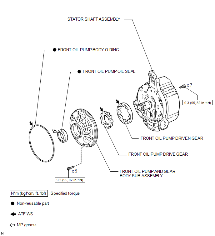
 Oil Pump
...
 Disassembly
DISASSEMBLY
PROCEDURE
1. INSPECT FRONT OIL PUMP AND GEAR BODY SUB-ASSEMBLY
2. REMOVE STATOR SHAFT ASSEMBLY
(a) Using a "TORX" wrench (T30), remove the 16 bolts and stator s ...
Other materials about Toyota Venza:
Television Camera
Components
COMPONENTS
ILLUSTRATION
ILLUSTRATION
Removal
REMOVAL
PROCEDURE
1. REMOVE BACK DOOR PANEL TRIM ASSEMBLY
2. REMOVE REAR WIPER ARM HEAD CAP
3. REMOVE REAR WIPER ARM AND BLADE ASSEMBLY
4. REMOVE REAR WIPER MOTOR GROMMET
5. ...
Rear Wheel House Plate
Components
COMPONENTS
ILLUSTRATION
Installation
INSTALLATION
PROCEDURE
1. INSTALL NO. 2 ROCKER PANEL MOULDING PROTECTOR
(a) Install the No. 2 rocker panel moulding protector with the 2 screws
<B>.
...
Trip information
Display items can be switched by pressing the “INFO-CLOCK” button.
- Average fuel consumption (AVERAGE ECON)
Displays the average fuel consumption since the function was reset.
• The
function can be reset by pressing and holding the “RESET ...

0.1352