Toyota Venza: Rear Wheel House Plate
Components
COMPONENTS
ILLUSTRATION
Installation
INSTALLATION
PROCEDURE
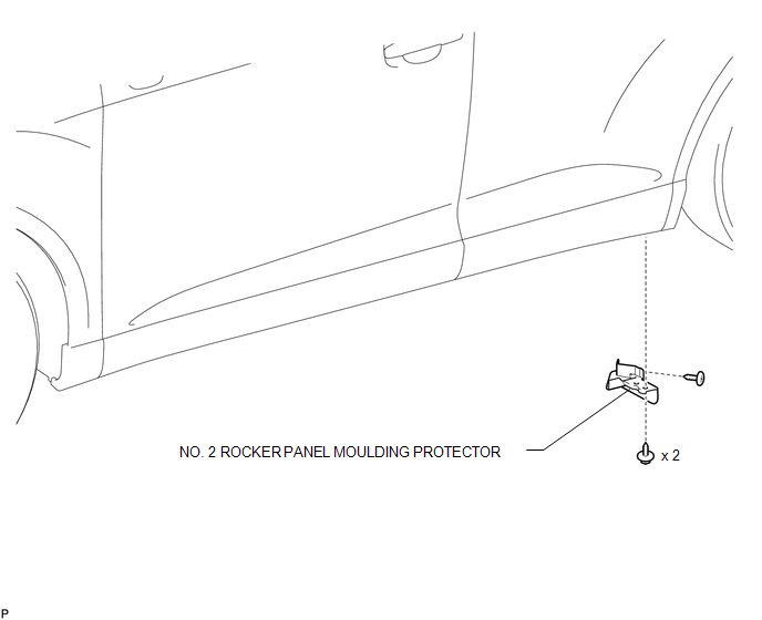
1. INSTALL NO. 2 ROCKER PANEL MOULDING PROTECTOR
|
(a) Install the No. 2 rocker panel moulding protector with the 2 screws <B>. |
|
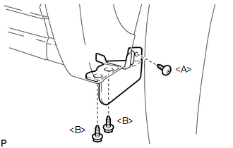
(b) Install the screw <A>.
Removal
REMOVAL
PROCEDURE
1. REMOVE NO. 2 ROCKER PANEL MOULDING PROTECTOR
|
(a) Remove the screw <A>. |
|
.png)
(b) Remove the 2 screws <B> and remove the No. 2 rocker panel moulding protector.
 Rear Spoiler
Components
COMPONENTS
ILLUSTRATION
Removal
REMOVAL
PROCEDURE
1. REMOVE UPPER BACK WINDOW PANEL TRIM
2. REMOVE REAR SPOILER ASSEMBLY
(a) Disconnect the connector.
...
 Rocker Panel Moulding
Components
COMPONENTS
ILLUSTRATION
Removal
REMOVAL
PROCEDURE
1. REMOVE FRONT FENDER OUTSIDE MOULDING
2. REMOVE NO. 2 ROCKER PANEL MOULDING PROTECTOR
3. REMOVE REAR ROCKER PANEL MOU ...
Other materials about Toyota Venza:
Driver Side Power Window does not Operate with Power Window Master Switch
DESCRIPTION
When the engine is running or the ignition switch is ON, the power window regulator
motor assembly (for driver side) is operated by the power window regulator master
switch assembly. The power window regulator motor assembly (for driver side) ...
Front Wiper Rubber
Components
COMPONENTS
ILLUSTRATION
Replacement
REPLACEMENT
PROCEDURE
1. REMOVE FRONT WIPER BLADE
(a) Remove the holder of the front wiper blade.
(b) Remove the front wiper blade from the f ...
Power Management Control ECU Communication Stop Mode
DESCRIPTION
Detection Item
Symptom
Trouble Area
Power Management Control ECU Communication Stop Mode
"Electric Power Control" is not displayed on the CAN Bus Check
screen ...

0.1437