Toyota Venza: Transmission Range Sensor Circuit Malfunction (PRNDL Input) (P0705)
DESCRIPTION
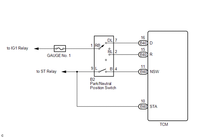
The park/neutral position switch detects the shift lever position and sends signals to the TCM.
|
DTC No. |
DTC Detection Condition |
Trouble Area |
|---|---|---|
|
P0705 |
(A) Any 2 or more signals of the following are ON simultaneously (2-trip detection logic)
(B) All switches are OFF simultaneously for NSW, R and D. |
|
MONITOR DESCRIPTION
These DTCs indicate a problem with the park/neutral position switch and the wire harness in the park/neutral position switch circuit.
The park/neutral position switch detects the shift lever position and sends signals to the TCM.
For safety, the park/neutral position switch detects the shift lever position so that the engine can be started only when the shift lever is in P or N.
The park/neutral position switch sends a signal to the TCM according to the shift lever position (R or D). The TCM determines that there is a problem with the switch or related parts if it receives more than 1 position signal simultaneously. The TCM will turn on the MIL and store the DTC.
MONITOR STRATEGY
|
Related DTCs |
P0705: Park/neutral position switch/Verify switch input |
|
Required sensors/Components |
Park/neutral position switch |
|
Frequency of operation |
Continuous |
|
Duration |
Condition (A): 2 sec. Condition (B): 60 sec. |
|
MIL operation |
2 driving cycles |
|
Sequence of operation |
None |
TYPICAL ENABLING CONDITIONS
|
The monitor will run whenever the following DTCs are not present |
None |
|
Ignition switch |
ON |
|
Battery voltage |
10.5 V or more |
|
Starter |
OFF |
TYPICAL MALFUNCTION THRESHOLDS
- When either condition below is met: Condition (A) or (B)
Condition (A)
- When 2 or more of the following signals are input at the same
time:
Park neutral position switch
ON
R position switch
ON
D position switch
ON
Condition (B)- When all conditions below are met:
Park neutral position switch
OFF
R position switch
OFF
D position switch
OFF
- When 2 or more of the following signals are input at the same
time:
COMPONENT OPERATING RANGE
|
Park/neutral position switch |
The park/neutral position switch sends only one signal to the TCM |
WIRING DIAGRAM
CAUTION / NOTICE / HINT
NOTICE:
Perform the universal trip to clear permanent DTCs (See page
.gif) ).
).
HINT:
Using the Techstream to read the Data List allows the values or states of switches, sensors, actuators and other items to be read without removing any parts. This non-intrusive inspection can be very useful because intermittent conditions or signals may be discovered before parts or wiring is disturbed. Reading the Data List information early in troubleshooting is one way to save diagnostic time.
NOTICE:
In the table below, the values listed under "Normal Condition" are reference values. Do not depend solely on these reference values when deciding whether a part is faulty or not.
- Warm up the engine.
- Turn the ignition switch off.
- Connect the Techstream to the DLC3.
- Turn the ignition switch to ON.
- Turn the Techstream on.
- Enter the following menus: Powertrain / ECT / Data List.
- According to the display on the Techstream, read the Data List.
Tester Display
Measurement Item / Range
Normal Condition
Diagnostic Note
Neutral Position SW Signal
PNP switch status / ON or OFF
- ON: Shift lever is in P or N
- OFF: Shift lever is not in P or N
When the shift lever position displayed on the Techstream differs from the actual position, adjustment of the PNP switch or the shift cable may be incorrect.
Shift SW Status (R Range)
PNP switch status / ON or OFF
- ON: Shift lever is in R
- OFF: Shift lever is not in R
When the shift lever position displayed on the Techstream differs from the actual position, adjustment of the PNP switch or the shift cable may be incorrect.
Shift SW Status (D Range)
PNP switch status / ON or OFF
- ON: Shift lever is in D or S
- OFF: Shift lever is not in D or S
When the shift lever position displayed on the Techstream differs from the actual position, adjustment of the PNP switch or the shift cable may be incorrect.
PROCEDURE
|
1. |
CHECK HARNESS AND CONNECTOR (BATTERY - PARK/NEUTRAL POSITION SWITCH) |
|
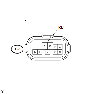
(a) Disconnect the park/neutral position switch connector. |
|
(b) Turn the ignition switch to ON.
(c) Measure the voltage according to the value(s) in the table below.
Standard Voltage:
|
Tester Connection |
Switch Condition |
Specified Condition |
|---|---|---|
|
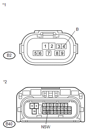
B2-1 (RB) - Body ground |
Ignition switch ON |
11 to 14 V |
|
*1 |
Front view of wire harness connector (to Park/Neutral Position Switch) |
| NG | .gif) |
REPAIR OR REPLACE HARNESS OR CONNECTOR |
|
.gif)
|
2. |
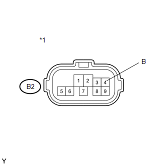
CHECK HARNESS AND CONNECTOR (OUTPUT SIGNAL) |
|
(a) Turn the ignition switch to ON. |
|
(b) Measure the voltage according to the value(s) in the table below.
Standard Voltage:
|
Tester Connection |
Switch Condition |
Specified Condition |
|---|---|---|
|
B2-4 (B) - Body ground |
Ignition switch ON |
11 to 14 V |
|
*1 |
Front view of wire harness connector (to Park/Neutral Position Switch) |
| NG | |
GO TO STEP 5 |
|
|
3. |
INSPECT PARK/NEUTRAL POSITION SWITCH ASSEMBLY |
|
(a) Disconnect the park/neutral position switch connector. |
|
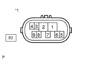
(b) Measure the resistance according to the value(s) in the table below when the shift lever is moved to each position.
Standard Resistance:
|
Tester Connection |
Shift Lever Position |
Specified Condition |
|---|---|---|
|
4 - 9 |
P or N |
Below 1 Ω |
|
Except P and N |
10 Ω or higher |
|
|
1 - 2 |
R |
Below 1 Ω |
|
Except R |
10 Ω or higher |
|
|
1 - 7 |
D, S, "+" or "-" |
Below 1 Ω |
|
Except D, S, "+" and "-" |
10 Ω or higher |
|
*1 |
Component without harness connected (Park/Neutral Position Switch) |
| NG | |
REPLACE PARK/NEUTRAL POSITION SWITCH ASSEMBLY |
|
|
4. |
CHECK HARNESS AND CONNECTOR (PARK/NEUTRAL POSITION SWITCH - TCM) |
|
(a) Connect the park/neutral position switch connector. |
|
(b) Disconnect the TCM connectors.
(c) Turn the ignition switch to ON, and measure the voltage according to the value(s) in the table below when the shift lever is moved to each position.
Standard Voltage:
|
Tester Connection |
Shift Lever Position |
Specified Condition |
|---|---|---|
|
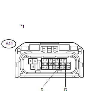
B40-15 (R) - Body ground |
R |
11 to 14 V* |
|
Except R |
Below 1 V |
|
|
B40-16 (D) - Body ground |
D, S, "+" or "-" |
11 to 14 V |
|
Except D, S, "+" and "-" |
Below 1 V |
|
*1 |
Front view of wire harness connector (to TCM) |
HINT:
*: The voltage will drop slightly due to lighting up of the back up light.
| OK | |
REPLACE TCM |
| NG | |
REPAIR OR REPLACE HARNESS OR CONNECTOR |
|
5. |
CHECK HARNESS AND CONNECTOR (PARK/NEUTRAL POSITION SWITCH - TCM) |
(a) Turn the ignition switch off.
(b) Disconnect the TCM connector.
(c) Disconnect the park/neutral position switch connector.
|
(d) Measure the resistance according to the value(s) in the table below. Standard Resistance (Check for Open):
Standard Resistance (Check for Short):
|
|
| OK | |
REPLACE TCM |
| NG | |
REPAIR OR REPLACE HARNESS OR CONNECTOR |
 Transmission Fluid Temperature Sensor "A" Circuit Low Input (P0712,P0713)
DESCRIPTION
The Automatic Transmission Fluid (ATF) temperature sensor converts the fluid
temperature into a resistance value for use by the TCM.
The TCM applies a voltage to the temperature sens ...
 Internal Control Module EEPROM Error (P062F)
DESCRIPTION
The TCM monitors its internal operation and it will set this DTC when it detects
an internal malfunction.
DTC No.
DTC Detection Condition
Trouble Area
...
Other materials about Toyota Venza:
Removal
REMOVAL
PROCEDURE
1. REMOVE REAR BUMPER PLATE LH
(a) Using a screwdriver with the tip wrapped with protective tape, disengage
the 2 claws and remove the rear bumper plate LH.
Text in Illustration
*1
Pro ...
Precaution
PRECAUTION
1. PRECAUTION FOR DISCONNECTING THE BATTERY CABLE
NOTICE:
When disconnecting the cable from the negative (-) battery terminal, initialize
the following systems after the terminal is reconnected.
System Name
See Procedure
...
Inspection
INSPECTION
PROCEDURE
1. INSPECT UNIVERSAL JOINT SPIDER ASSEMBLY
(a) Check the spider bearing axial play by turning the flange while holding
the shaft tightly.
HINT:
If necessary, replace the propeller with center bearing shaft assembly. ...

0.12