Toyota Venza: Removal
REMOVAL
CAUTION / NOTICE / HINT
HINT:
- Use the same procedure for the RH side and LH side.
- The procedure listed below is for the LH side.
PROCEDURE
1. REMOVE REAR WHEEL
2. SEPARATE REAR DISC BRAKE CALIPER ASSEMBLY
.gif)
3. REMOVE REAR DISC
4. SEPARATE REAR SPEED SENSOR WIRE
5. SEPARATE NO. 3 PARKING BRAKE CABLE ASSEMBLY
6. REMOVE REAR AXLE HUB AND BEARING ASSEMBLY
7. REMOVE REAR STRUT ROD ASSEMBLY
8. REMOVE REAR AXLE CARRIER SUB-ASSEMBLY
|
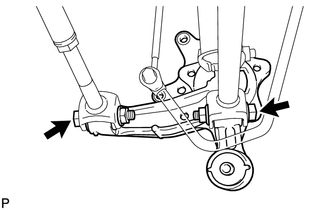
(a) Loosen the 2 bolts. NOTICE: Since stopper nuts are used, loosen the bolts. |
|
|
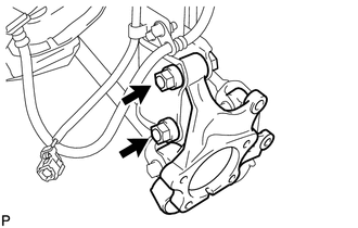
(b) Remove the 2 bolts and 2 nuts, and separate the rear axle carrier sub-assembly from the rear shock absorber with coil spring. NOTICE: When removing the nuts, keep the bolts from rotating. |
|
|
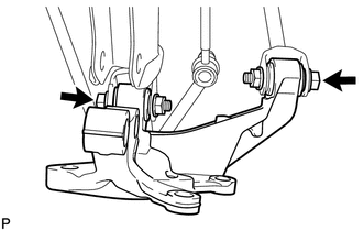
(c) Remove the 2 bolts, 2 nuts and rear axle carrier sub-assembly. |
|
 Components
COMPONENTS
ILLUSTRATION
...
 Installation
INSTALLATION
CAUTION / NOTICE / HINT
HINT:
Use the same procedure for the RH side and LH side.
The procedure listed below is for the LH side.
PROCEDURE
1. INSTALL REAR AXLE CARR ...
Other materials about Toyota Venza:
Power Mirror cannot be Adjusted with Power Mirror Switch
SYSTEM DESCRIPTION
The main body ECU (driver side junction block assembly) detects the mirror adjust
switch status and sends the signal to the outer mirror control ECU assembly via
CAN communication. On receiving the signal, each outer mirror control ECU ...
Compressor Lock Sensor Circuit (B1422/22)
SYSTEM DESCRIPTION
The ECM sends the engine speed signal to the A/C amplifier via CAN communication.
The A/C amplifier reads the difference between compressor speed and engine speed.
When the difference becomes too large, the A/C amplifier determines that ...
Personal Light
Components
COMPONENTS
ILLUSTRATION
Removal
REMOVAL
PROCEDURE
1. REMOVE MAP LIGHT ASSEMBLY
(a) Using a moulding remover, disengage the 2 claws and 2 clips.
Text in Illustration
*1
Fastener
...

0.1272