Toyota Venza: Components
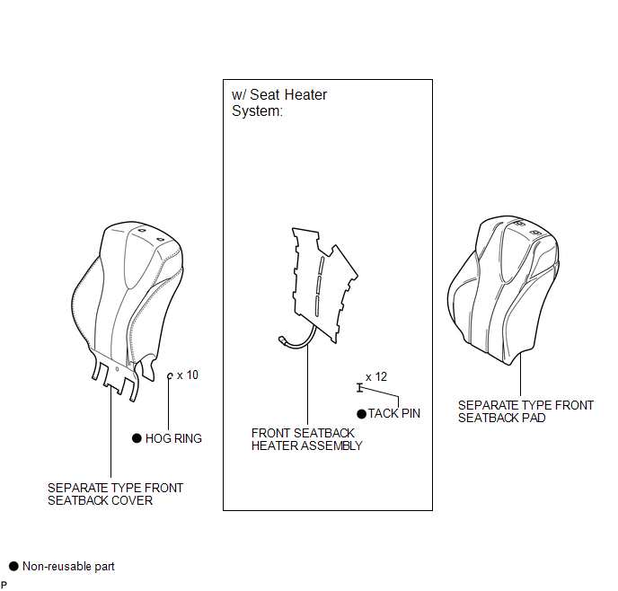
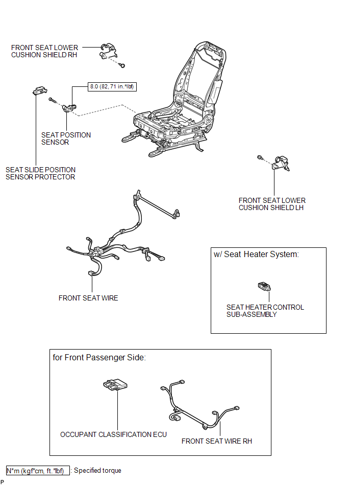
COMPONENTS
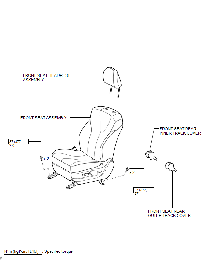
ILLUSTRATION
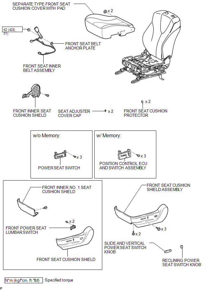
ILLUSTRATION
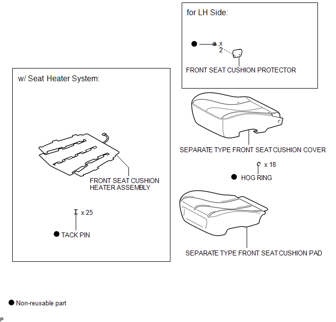
ILLUSTRATION
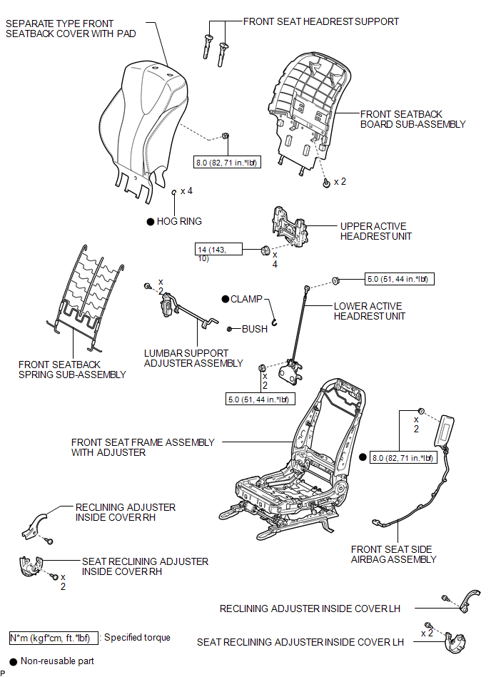
ILLUSTRATION
ILLUSTRATION
ILLUSTRATION

 Removal
REMOVAL
PROCEDURE
1. PRECAUTION
CAUTION:
Be sure to read Precaution thoroughly before servicing (See page
).
If the front seat side airbag assembly was deployed, replace the front ...
Other materials about Toyota Venza:
Mass Air Flow Meter
Components
COMPONENTS
ILLUSTRATION
On-vehicle Inspection
ON-VEHICLE INSPECTION
CAUTION / NOTICE / HINT
NOTICE:
Perform the mass air flow meter inspection according to the procedure
below.
Only replace the mass air flow meter when t ...
Reassembly
REASSEMBLY
PROCEDURE
1. INSTALL NO. 2 STEERING RACK BOOT
(a) Apply lithium soap base glycol grease to the inside of the small
opening of a new No. 2 steering rack boot.
(b) Install the No. 2 ste ...
On-vehicle Inspection
ON-VEHICLE INSPECTION
PROCEDURE
1. INSPECT HOOD SUB-ASSEMBLY
(a) Check that the clearance measurements of areas *1 through *4 are within each
standard range.
Standard Clearance
Area
Measurement
Area
Measureme ...

0.1553