Toyota Venza: Removal
REMOVAL
PROCEDURE
1. PRECAUTION
CAUTION:
- Be sure to read Precaution thoroughly before servicing (See page
.gif) ).
). - If the front seat side airbag assembly was deployed, replace the front seat side airbag assembly, front seat frame assembly with adjuster, separate type front seatback cover and separate type front seatback pad with the necessary parts in accordance with the extent of the collision damage.
2. REMOVE FRONT SEAT HEADREST ASSEMBLY
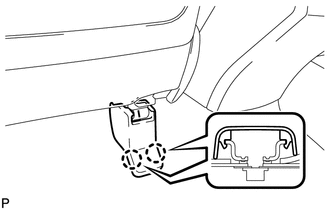
3. REMOVE FRONT SEAT REAR OUTER TRACK COVER
(a) Operate the slide and vertical power seat switch knob and move the front seat assembly to the foremost position.
|
(b) Disengage the 2 claws and remove the front seat rear outer track cover. |
|

4. REMOVE FRONT SEAT REAR INNER TRACK COVER
|
(a) Disengage the 2 claws and remove the front seat rear inner track cover. |
|
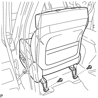
5. REMOVE FRONT SEAT ASSEMBLY
|
(a) Remove the 2 bolts on the rear side of the front seat assembly. |
|
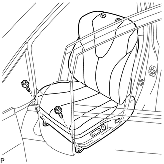
(b) Operate the slide and vertical power seat switch knob and move the front seat assembly to the rearmost position.
|
(c) Remove the 2 bolts on the front side of the front seat assembly. |
|
(d) Operate the slide and vertical power seat switch knob and move the front seat assembly to the center position. Also, operate the reclining power seat switch knob and move the front seatback assembly to the upright position.
(e) Disconnect the cable from the negative (-) battery terminal.
CAUTION:
Wait at least 90 seconds after disconnecting the cable from the negative (-) battery terminal to disable the SRS system.
NOTICE:
When disconnecting the cable, some systems need to be initialized after the cable
is reconnected (See page ).
(f) Disconnect each connector under the front seat assembly.
(g) Remove the front seat assembly.
NOTICE:
Be careful not to damage the vehicle body.
 Components
COMPONENTS
ILLUSTRATION
ILLUSTRATION
ILLUSTRATION
ILLUSTRATION
ILLUSTRATION
ILLUSTRATION
...
 Disassembly
DISASSEMBLY
PROCEDURE
1. REMOVE SEAT ADJUSTER COVER CAP
(a) Remove the seat adjuster cover cap.
HINT:
Use the same procedure for the RH side and LH side.
...
Other materials about Toyota Venza:
System Diagram
SYSTEM DIAGRAM
1. MIRROR CONTROL SYSTEM
Communication Table
Sender
Receiver
Signal / Signal Condition
Line
Main body ECU (driver side junction block assembly)
Outer mirror control EC ...
Removal
REMOVAL
PROCEDURE
1. PRECAUTION
CAUTION:
Be sure to read Precaution thoroughly before servicing (See page
).
If the front seat side airbag assembly was deployed, replace the front
seat side airbag assembly, front seat frame assembly wit ...
Battery
- Battery exterior
Make sure that the battery terminals are not corroded and that there are no loose
connections, cracks, or loose clamps.
1. Terminals
2. Hold-down clamp
- Before recharging
When recharging, the battery produces hydrogen g ...

0.1845