Toyota Venza: System Diagram
SYSTEM DIAGRAM
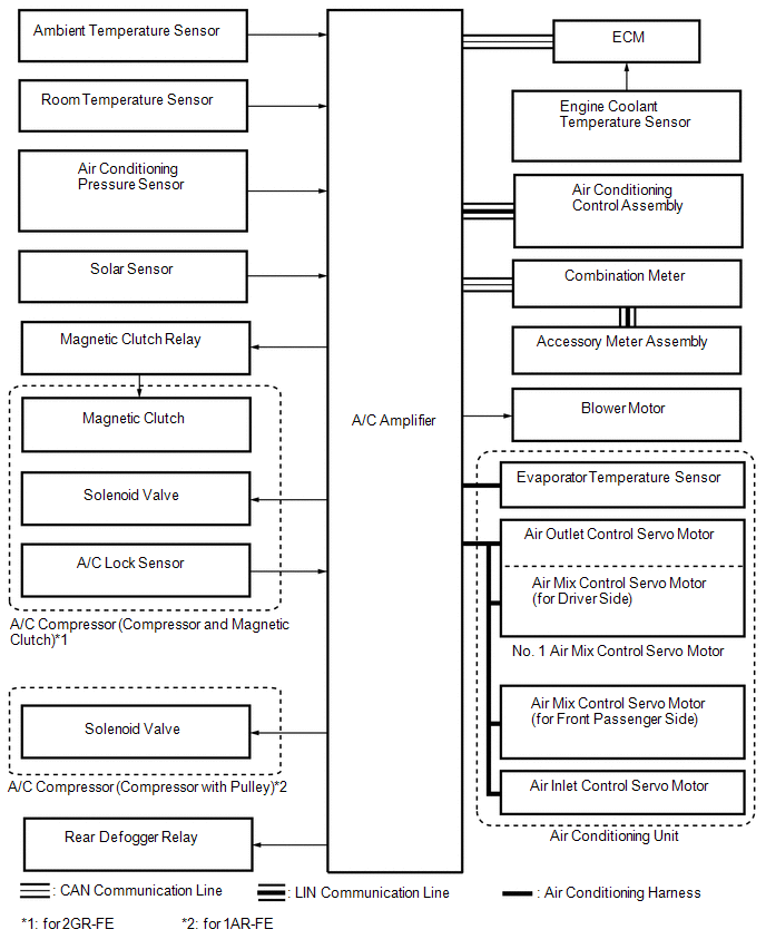 Communication Table
|
Sender |
Receiver |
Signal |
Communication Line |
|---|---|---|---|
|
A/C amplifier |
ECM |
Magnetic clutch request signal*1 |
CAN |
|
Idle up request signal |
|||
|
External variable control solenoid current signal |
|||
|
Cooling fan motor driving request signal |
|||
|
Refrigerant gas pressure sensor signal |
|||
|
Ambient temperature signal |
|||
|
A/C amplifier |
Air conditioning control assembly |
Panel indication signal |
LIN |
|
MODE indication signal |
|||
|
Blower level indication signal |
|||
|
Set temperature indication signal |
|||
|
Combination meter |
A/C amplifier |
Vehicle speed signal |
CAN |
|
ECM |
A/C amplifier |
Engine revolution speed signal |
CAN |
|
Engine coolant temperature signal |
|||
|
A/C control cut signal |
|||
|
Air conditioning control assembly |
A/C amplifier |
AUTO switch signal |
LIN |
|
OFF switch signal |
|||
|
A/C switch signal |
|||
|
Fr DEF switch signal |
|||
|
Rr DEF switch signal |
|||
|
MODE switch signal |
|||
|
REC/FRS switch signal |
|||
|
SYNC switch signal |
|||
|
Blower switch signal (FAN+, FAN-) |
|||
|
Set temperature switch signal (UP, DOWN) |
- *1: for 2GR-FE
 Parts Location
PARTS LOCATION
ILLUSTRATION
ILLUSTRATION
ILLUSTRATION
...
 System Description
SYSTEM DESCRIPTION
1. GENERAL
(a) The air conditioning system has the following controls.
Control
Outline
Neural Network Control
This control is ca ...
Other materials about Toyota Venza:
Data Signal Circuit between Navigation Receiver Assembly and Stereo Jack Adapter
DESCRIPTION
The No. 1 stereo jack adapter assembly sends the sound data signal or image data
signal from a USB device to the navigation receiver assembly via this circuit.
WIRING DIAGRAM
PROCEDURE
1.
CHECK HARNESS AND CONNECTOR ( ...
Audio system types
► Vehicles with Display Audio system
Type A
Type B
Refer to the “Display Audio System Owner’s Manual”.
► Vehicles with a navigation system
Refer to the “Navigation System Owner’s Manual”. ...
Removal
REMOVAL
CAUTION / NOTICE / HINT
HINT:
Use the same procedure for the LH side and RH side.
The following procedure is for the LH side.
If the sensor rotor needs to be replaced, replace it together with the
front drive shaft assembly.
...

0.1813