Toyota Venza: Head restraints
Head restraints are provided for all seats.
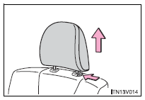
► Front and rear outboard seats
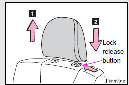
Vertical adjustment 1. Up Pull the head restraint up.
2. Down
Push the head restraints down while pressing the lock release button.
► Rear center seat (fabric seat)
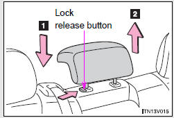
Vertical adjustment 1. Down 2. Up
Push the head restraint up or down while pressing the lock release button.
► Rear center seat (leather seat)
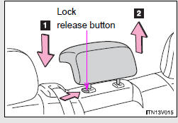
Vertical adjustment 1. Down Push the head restraint down while pressing the lock release button.
2. Up
Pull the head restraint up.
- Adjusting the height of the head restraints
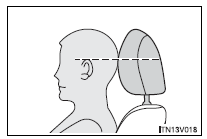
Make sure that the head restraints are adjusted so that the center of the head restraint is closest to the top of your ears.
- Adjusting the rear center seat head restraint
Always raise the head restraint one level from the stowed position when using.
- Removing the head restraints
Pull the head restraint up while pressing the lock release button.
- Installing the head restraints
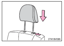
Align the head restraint with the installation holes and push it down to the lock position.
Press and hold the lock release button when lowering the head restraint.
CAUTION
- Head restraint precautions
Observe the following precautions regarding the head restraints. Failure to do so may result in death or serious injury.
• Use the head restraints designed for each respective seat.
• Adjust the head restraints to the correct position at all times.
• After adjusting the head restraints, push down on them and make sure they are locked in position.
• Do not drive with the head restraints removed.
 Driving position memory
Your preferred driving position (the position of the driver’s seat and angle
of the outside rear view mirrors) can be memorized and recalled by pressing a button.
It is also possible to set this ...
 Seat belts
Make sure that all occupants are wearing their seat belts before driving the
vehicle.
- Correct use of the seat belts
1. Extend the shoulder belt so that it comes fully over the shoulder, ...
Other materials about Toyota Venza:
Problem Symptoms Table
PROBLEM SYMPTOMS TABLE
HINT:
Use the table below to help determine the cause of problem symptoms.
If multiple suspected areas are listed, the potential causes of the symptoms
are listed in order of probability in the "Suspected Area" ...
Removal
REMOVAL
CAUTION / NOTICE / HINT
HINT:
Use the same procedure for the LH side and RH side.
The following procedure listed is for the LH side.
PROCEDURE
1. REMOVE FRONT WHEEL
2. DRAIN BRAKE FLUID
NOTICE:
If brake fluid leaks onto any pa ...
Reassembly
REASSEMBLY
PROCEDURE
1. INSTALL GENERATOR ROTOR ASSEMBLY
(a) Place the generator drive end frame on the generator pulley.
(b) Install the generator rotor to the generator drive end frame.
...

0.1378