Toyota Venza: Components
COMPONENTS
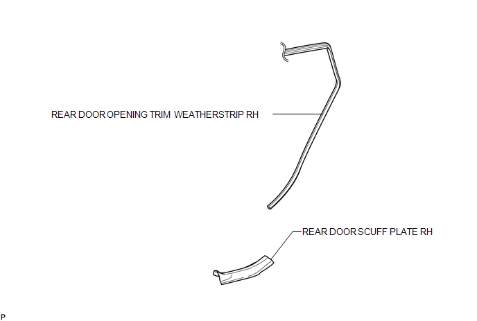
ILLUSTRATION
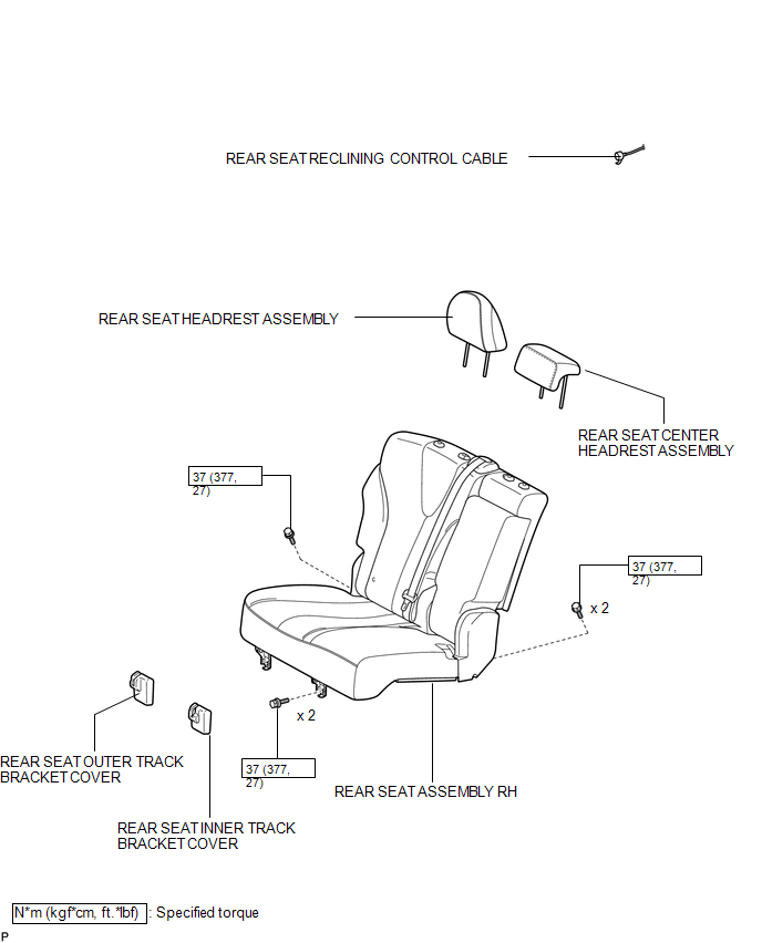
ILLUSTRATION
.png)
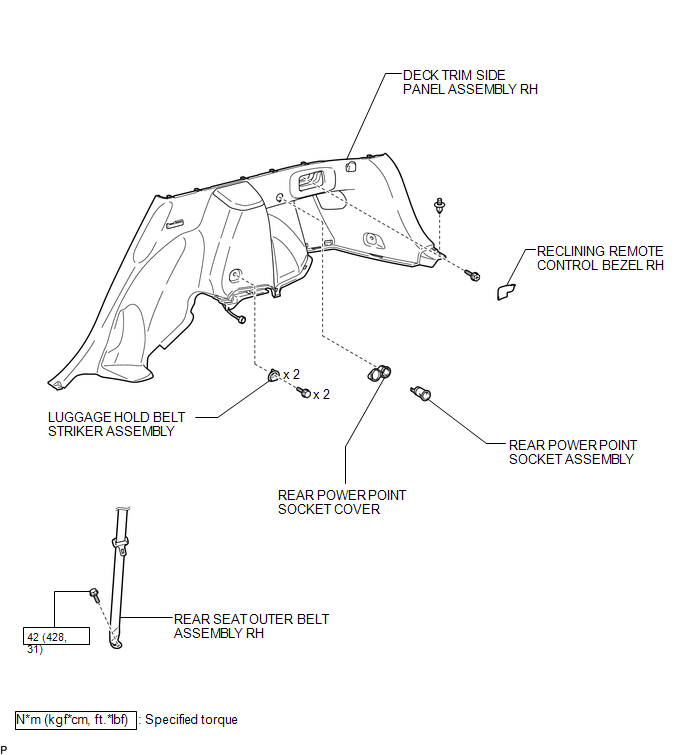
ILLUSTRATION
ILLUSTRATION

 Installation
INSTALLATION
PROCEDURE
1. INSTALL REAR POWER POINT SOCKET COVER
(a) Engage the 2 claws to install the rear power point socket cover.
2. IN ...
Other materials about Toyota Venza:
Speaker Output Short (B15C3)
DESCRIPTION
This DTC is stored when a malfunction occurs in the speakers.
DTC No.
DTC Detection Condition
Trouble Area
B15C3
A short is detected in the speaker output circuit.
...
Components
COMPONENTS
ILLUSTRATION
ILLUSTRATION
ILLUSTRATION
ILLUSTRATION
ILLUSTRATION
ILLUSTRATION
ILLUSTRATION
ILLUSTRATION
...
Problem Symptoms Table
PROBLEM SYMPTOMS TABLE
HINT:
Use the table below to help determine the cause of problem symptoms. If multiple
suspected areas are listed, the potential causes of the symptoms are listed in order
of probability in the "Suspected Area" column of ...

0.1611