
Toyota Venza: Engine
General Maintenance
GENERAL MAINTENANCE
CAUTION / NOTICE / HINT
HINT:
Perform these procedures after the engine has cooled down.
PROCEDURE
1. INSPECT DRIVE BELT
|
Engine Type |
See Procedure |
|---|---|
|
2GR-FE |
See page |
|
1AR-FE |
See page |
.gif)
2. REPLACE ENGINE OIL AND OIL FILTER
|
Engine Type |
See Procedure |
|---|---|
|
2GR-FE |
See page |
|
1AR-FE |
See page |
3. REPLACE ENGINE COOLANT
|
Engine Type |
See Procedure |
|---|---|
|
2GR-FE |
See page |
|
1AR-FE |
See page |
4. INSPECT SPARK PLUGS
|
Engine Type |
See Procedure |
|---|---|
|
2GR-FE |
See page |
|
1AR-FE |
See page |
5. INSPECT BATTERY
|
Engine Type |
See Procedure |
|---|---|
|
2GR-FE |
See page |
|
1AR-FE |
See page |
6. INSPECT AIR CLEANER FILTER ELEMENT
(a) Remove the air filter.
|
(b) Check that the air cleaner is not excessively dirty. If the air cleaner is excessively dirty, replace the air cleaner filter element. |
|
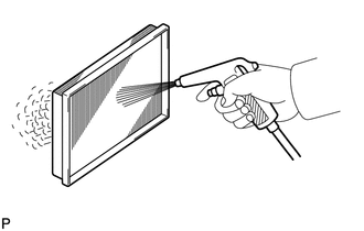
(c) If cleaning the air cleaner filter element, blow compressed air as shown in the illustration to clean it.
(d) Reinstall the air filter.
7. INSPECT EXHAUST PIPES AND MOUNTINGS
(a) Visually check the pipes, hangers and connections for severe corrosion, leaks or damage.
8. INSPECT FUEL TANK CAP GASKET
|
Engine Type |
See Procedure |
|---|---|
|
2GR-FE |
See page |
|
1AR-FE |
See page |
9. INSPECT FUEL LINES, CONNECTIONS, FUEL TANK VAPOR VENT SYSTEM HOSES AND FUEL TANK BANDS
(a) Visually check the fuel lines and hoses for cracks, leaks, loose connections or deformation.
(b) Check for tank band looseness or deformation.
10. INSPECT CHARCOAL CANISTER
|
Engine Type |
See Procedure |
|---|---|
|
2GR-FE |
See page |
|
1AR-FE |
See page |
 Chassis
General Maintenance
GENERAL MAINTENANCE
PROCEDURE
1. INSPECT STEERING LINKAGE AND GEAR HOUSING
(a) Check the steering wheel free play (See page
).
(b) Check the steering linkage for looseness ...
 Inside Vehicle
General Maintenance
GENERAL MAINTENANCE
CAUTION / NOTICE / HINT
These are maintenance and inspection items that are considered to be
the owner's responsibility.
The owner can do ...
Other materials about Toyota Venza:
ECU Power Source Circuit
DESCRIPTION
This is the power source for the tire pressure warning ECU.
WIRING DIAGRAM
CAUTION / NOTICE / HINT
NOTICE:
When replacing the tire pressure warning ECU, read the transmitter IDs
stored in the old ECU using the Techstream and writ ...
Panel Switches do not Function
PROCEDURE
1.
CHECK PANEL SWITCH
(a) Check for foreign matter around the switches that might prevent operation.
OK:
No foreign matter is found.
NG
REMOVE ANY FOREIGN MATTER FOUND
...
Sensor (Motor) Failure (B2341,B2344)
DESCRIPTION
When the sliding roof ECU (sliding roof drive gear sub-assembly) detects a motor
malfunction and the sliding roof operation is stopped, DTC B2341 is output.
When the sliding roof ECU (sliding roof drive gear sub-assembly) detects a gear
malfu ...

0.1364